C O M M E R C I A L | P R O D U C T S | D I V I S I O N | |
Diagram 15 | Secure the |
|
|
| fasteners. |
|
|
| Second: |
|
|
| Alternately | 2 |
|
| tighten four side |
| |
| upright screws. |
|
|
| First: Alternately |
|
|
| tighten four front |
| 3 |
| panel screws. |
| |
| Third: Alternately |
|
|
| tighten the four |
|
|
| screws that | 1 |
|
| secure the |
| |
| console to the |
|
|
| uprights. |
|
|
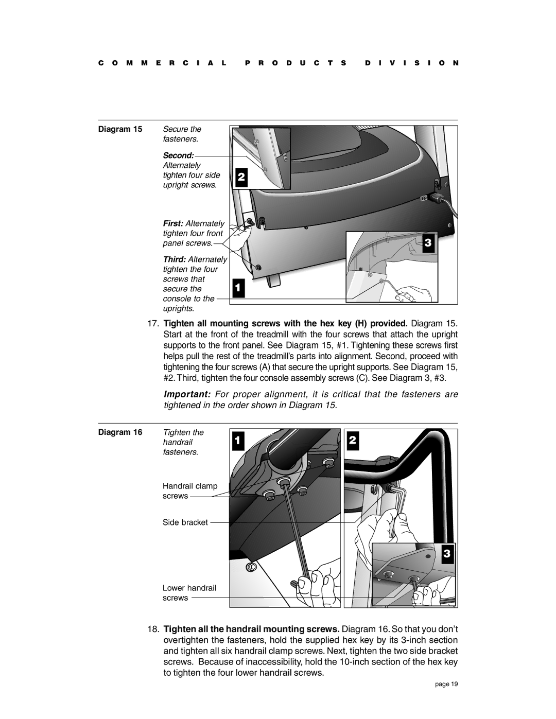
17.Tighten all mounting screws with the hex key (H) provided. Diagram 15. Start at the front of the treadmill with the four screws that attach the upright supports to the front panel. See Diagram 15, #1. Tightening these screws first helps pull the rest of the treadmill’s parts into alignment. Second, proceed with tightening the four screws (A) that secure the upright supports. See Diagram 15, #2. Third, tighten the four console assembly screws (C). See Diagram 3, #3.
Important: For proper alignment, it is critical that the fasteners are tightened in the order shown in Diagram 15.
Diagram 16 | Tighten the | 1 | 2 |
| handrail | ||
| fasteners. |
|
|
| Handrail clamp |
|
|
| screws |
|
|
| Side bracket |
|
|
|
|
| 3 |
| Lower handrail |
|
|
| screws |
|
|
18.Tighten all the handrail mounting screws. Diagram 16. So that you don’t overtighten the fasteners, hold the supplied hex key by its
page 19
