Assembling the Treadmill |
| 23 |
Component | Appearance | Lower connection |
|
| point |
Television cable | Round with black insulation |
|
Console power | Dual leads with red and |
|
cable | black insulation |
|
Auto Stop sensor | Round with black insulation |
|
cable |
|
|
Power supply | Rectangular, black, 5" x |
|
| 2¹₄" x 1¹₄" |
|
CAUTION: Be careful not to cut or pinch any wires during the following step.
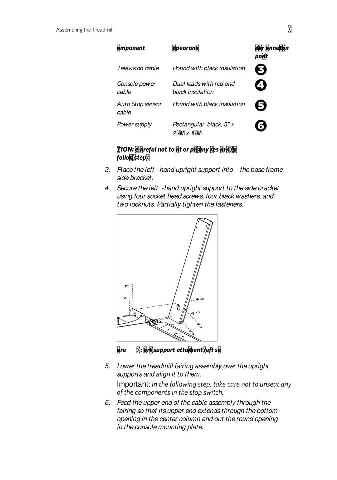
3.Place the
4.Secure the
Figure 9: Upright support attachment, left side
5.Lower the treadmill fairing assembly over the upright supports and align it to them.
Important: In the following step, take care not to unseat any of the components in the stop switch.
6.Feed the upper end of the cable assembly through the fairing so that its upper end extends through the bottom opening in the center column and out the round opening in the console mounting plate.
