I I I . I N S T A L L A T I O N
To raise or lower the boom arm:
1.Support the boom arm.
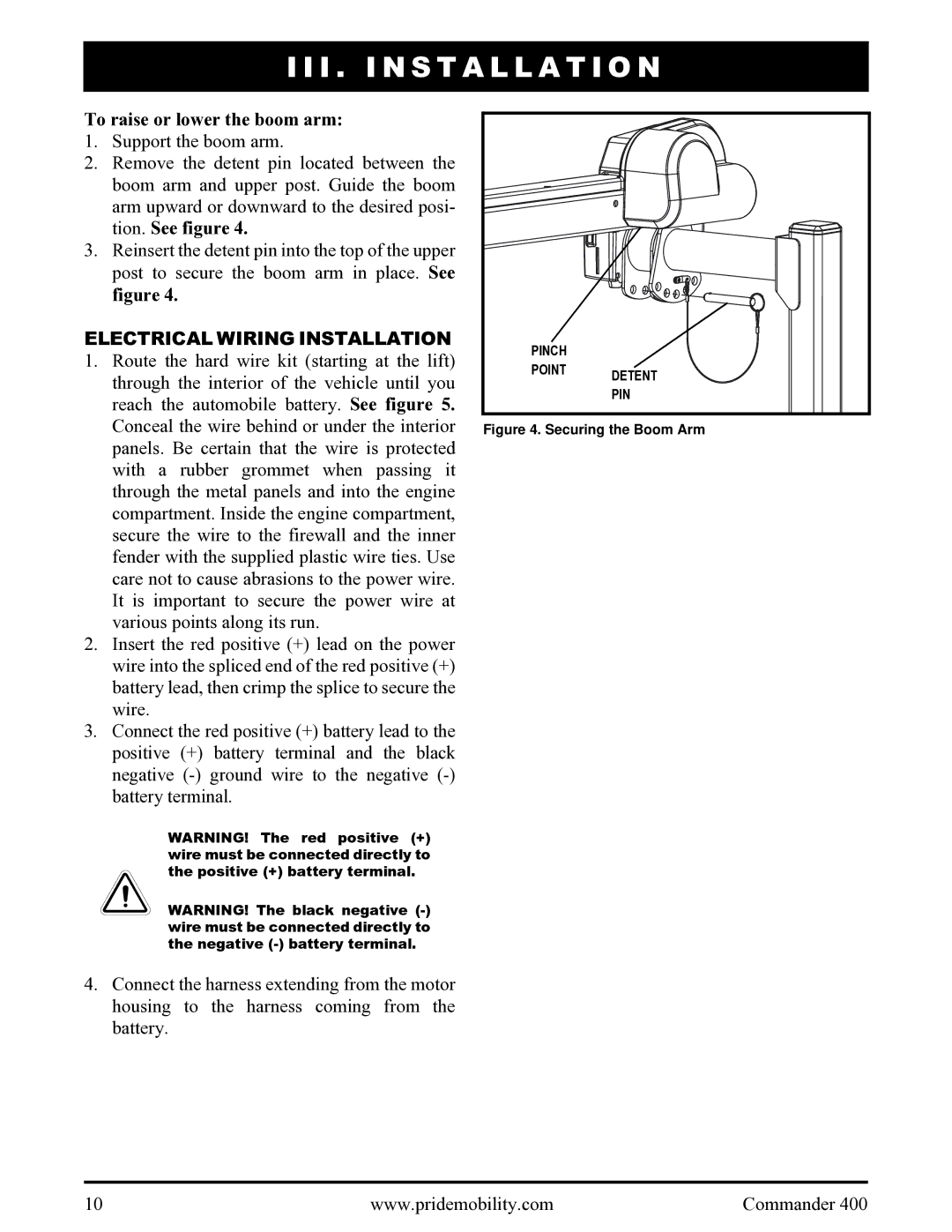
2.Remove the detent pin located between the boom arm and upper post. Guide the boom arm upward or downward to the desired posi- tion. See figure 4.
3.Reinsert the detent pin into the top of the upper post to secure the boom arm in place. See figure 4.
ELECTRICAL WIRING INSTALLATION
1.Route the hard wire kit (starting at the lift) through the interior of the vehicle until you reach the automobile battery. See figure 5. Conceal the wire behind or under the interior panels. Be certain that the wire is protected with a rubber grommet when passing it through the metal panels and into the engine compartment. Inside the engine compartment, secure the wire to the firewall and the inner fender with the supplied plastic wire ties. Use care not to cause abrasions to the power wire. It is important to secure the power wire at various points along its run.
2.Insert the red positive (+) lead on the power wire into the spliced end of the red positive (+) battery lead, then crimp the splice to secure the wire.
3.Connect the red positive (+) battery lead to the positive (+) battery terminal and the black negative
WARNING! The red positive (+) wire must be connected directly to the positive (+) battery terminal.
WARNING! The black negative
4.Connect the harness extending from the motor housing to the harness coming from the battery.
PINCH |
|
POINT | DETENT |
| |
| PIN |
Figure 4. Securing the Boom Arm
10 | www.pridemobility.com | Commander 400 |