INSPECTING BURNER

Check pilot flame pattern and burner flame pattern often.

PILOT FLAME PATTERN

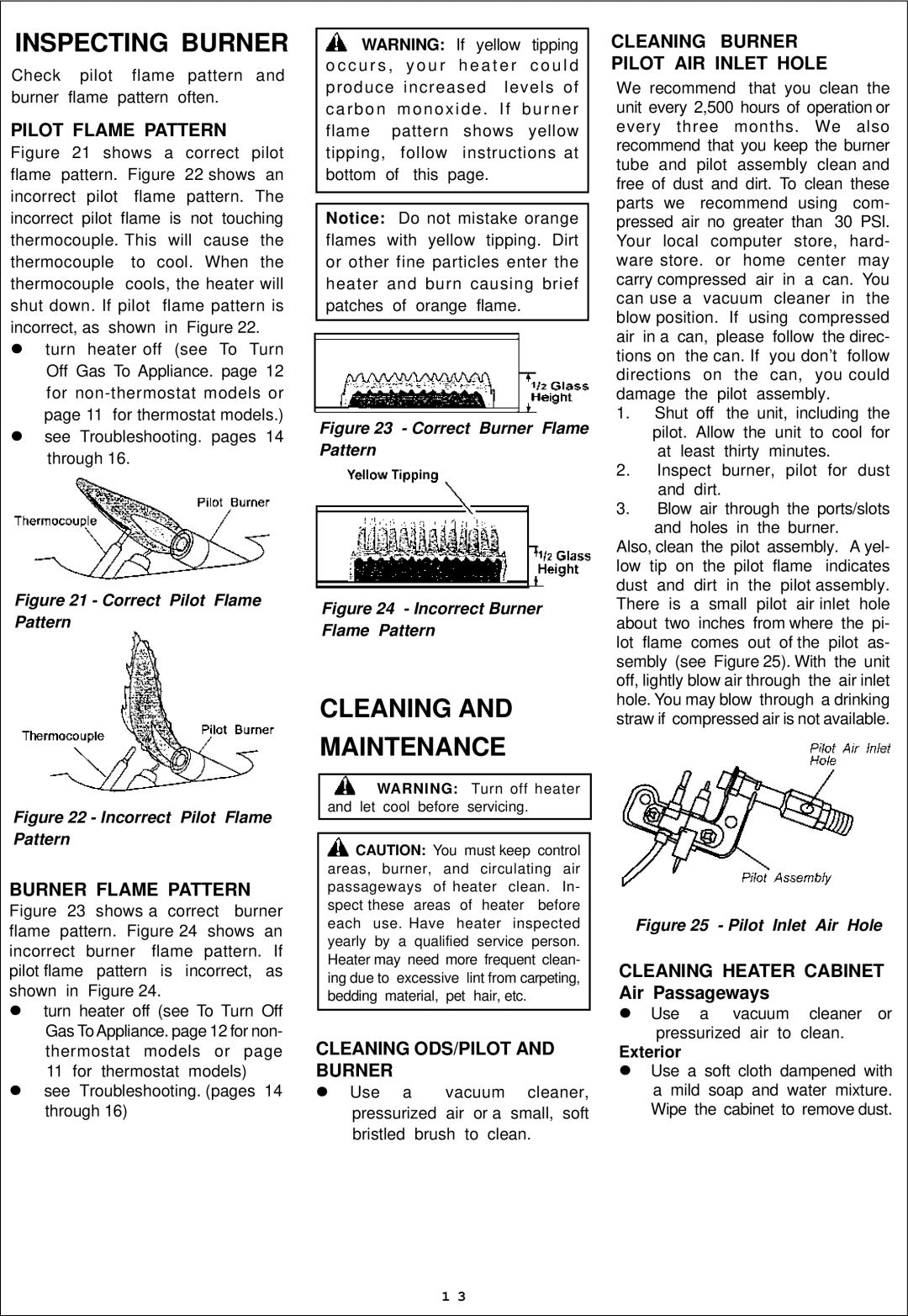
Figure 21 shows a correct pilot flame pattern. Figure 22 shows an incorrect pilot flame pattern. The incorrect pilot flame is not touching thermocouple. This will cause the thermocouple to cool. When the thermocouple cools, the heater will shut down. If pilot flame pattern is incorrect, as shown in Figure 22.

turn heater off (see To Turn Off Gas To Appliance. page 12 for non-thermostat models or page 11 for thermostat models.) see Troubleshooting. pages 14 through 16.

Figure 21 - Correct Pilot Flame Pattern

Figure 22 - Incorrect Pilot Flame Pattern

BURNER FLAME PATTERN

Figure 23 shows a correct burner flame pattern. Figure 24 shows an incorrect burner flame pattern. If pilot flame pattern is incorrect, as shown in Figure 24.

turn heater off (see To Turn Off Gas To Appliance. page 12 for non- thermostat models or page 11 for thermostat models) see Troubleshooting. (pages 14 through 16)

WARNING: If yellow tipping o c c u r s , y o u r h e a t e r c o u l d produce increased levels of carbon monoxide . If burner flame pattern shows yellow tipping, follow instructions at bottom of this page.

Notice: Do not mistake orange flames with yellow tipping. Dirt or other fine particles enter the heater and burn causing brief patches of orange flame.

Figure 23 - Correct Burner Flame Pattern

Figure 24 - Incorrect Burner Flame Pattern

CLEANING AND

MAINTENANCE

WARNING: Turn off heater and let cool before servicing.

CAUTION: You must keep control areas, burner, and circulating air passageways of heater clean. In- spect these areas of heater before each use. Have heater inspected yearly by a qualified service person. Heater may need more frequent clean- ing due to excessive lint from carpeting, bedding material, pet hair, etc.

CLEANING ODS/PILOT AND BURNER

Use a vacuum cleaner, pressurized air or a small, soft bristled brush to clean.

CLEANING BURNER PILOT AIR INLET HOLE

We recommend that you clean the unit every 2,500 hours of operation or every three months. We also recommend that you keep the burner tube and pilot assembly clean and free of dust and dirt. To clean these parts we recommend using com- pressed air no greater than 30 PSl. Your local computer store, hard- ware store. or home center may carry compressed air in a can. You can use a vacuum cleaner in the blow position. If using compressed air in a can, please follow the direc- tions on the can. If you don’t follow directions on the can, you could damage the pilot assembly.

1.Shut off the unit, including the pilot. Allow the unit to cool for at least thirty minutes.

2.Inspect burner, pilot for dust and dirt.

3.Blow air through the ports/slots and holes in the burner.

Also, clean the pilot assembly. A yel- low tip on the pilot flame indicates dust and dirt in the pilot assembly. There is a small pilot air inlet hole about two inches from where the pi- lot flame comes out of the pilot as- sembly (see Figure 25). With the unit off, lightly blow air through the air inlet hole. You may blow through a drinking straw if compressed air is not available.

Figure 25 - Pilot Inlet Air Hole

CLEANING HEATER CABINET Air Passageways

Use a vacuum cleaner or pressurized air to clean.

Exterior

Use a soft cloth dampened with a mild soap and water mixture. Wipe the cabinet to remove dust.

1 3

Page 13
Image 13
Procom ML200TBA, ML300HBA, ML300TBA Pilot Flame Pattern, Burner Flame Pattern, Cleaning ODS/PILOT and Burner, Exterior

ML200HBA, ML300TBA, ML300HBA, ML200TBA specifications

The Procom ML300HBA, ML200TBA, ML300TBA, and ML200HBA are innovative solutions designed to meet the demands of modern data management and communication environments. Each model is tailored for specific applications, ensuring versatility, performance, and reliability across various sectors.

The Procom ML300HBA is particularly highlighted for its expansive bandwidth capabilities, making it essential for high-data-rate applications. With a user-friendly interface, it supports multiple connections, enabling streamlined data flow and minimizing latency. Its built-in redundancy features ensure that data integrity is maintained, even in challenging conditions. This device is ideal for environments where continuous operation is critical, such as broadcasting and telecommunications.

In contrast, the Procom ML200TBA offers a robust solution for applications that require high-frequency signal transmission. It provides a compact design without compromising performance. The ML200TBA is engineered with advanced noise reduction technologies, allowing it to maintain signal quality even in densely populated frequency environments. This model is particularly suitable for use in urban settings or areas with high electromagnetic interference.

The Procom ML300TBA combines the best features of the aforementioned models, offering broad bandwidth alongside high-frequency capabilities. This dual functionality makes it a standout choice for users needing flexibility in their communication systems. The ML300TBA is also equipped with sophisticated thermal management systems, ensuring optimal performance under varying environmental conditions.

Finally, the Procom ML200HBA emphasizes durability and high performance in harsh environments. Its rugged design means it can withstand adverse weather conditions, making it an excellent choice for outdoor applications. The focus on reliability ensures that users can depend on the ML200HBA for critical operations without the fear of signal loss or degradation.

In summary, the Procom ML300HBA, ML200TBA, ML300TBA, and ML200HBA are distinguished by their specific features and technologies. Each model caters to unique demands, providing exceptional performance, reliability, and flexibility that make them invaluable in today's high-stakes data environments. Whether for broadcasting, telecommunications, or rugged outdoor communications, Procom’s ML series stands ready to deliver superior performance and adaptability.