ASSEMBLY
Assembly requires two persons.
Place all parts in a cleared area and remove the packing materials. Do not dispose of the packing materials until you complete all assembly steps.
To identify small parts, see page 5.
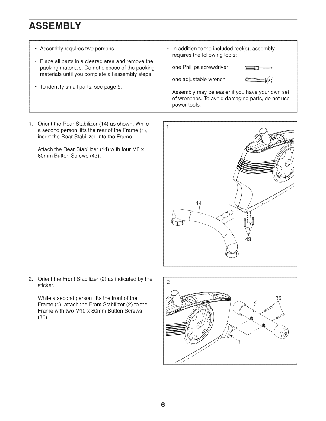
. Orient the Rear Stabilizer (14) as shown. While
a second person lifts the rear of the Frame (1), insert the Rear Stabilizer into the Frame.
Attach the Rear Stabilizer (14) with four M8 x 60mm Button Screws (43).
. Orient the Front Stabilizer (2) as indicated by the sticker.
While a second person lifts the front of the Frame (1), attach the Front Stabilizer (2) to the Frame with two M10 x 80mm Button Screws (36).
In addition to the included tool(s), assembly requires the following tools:
one Phillips screwdriver (]_z;======_
one adjustable wrench
Assembly may be easier if you have your own set of wrenches. To avoid damaging parts, do not use power tools.
141.-.
43
36
6