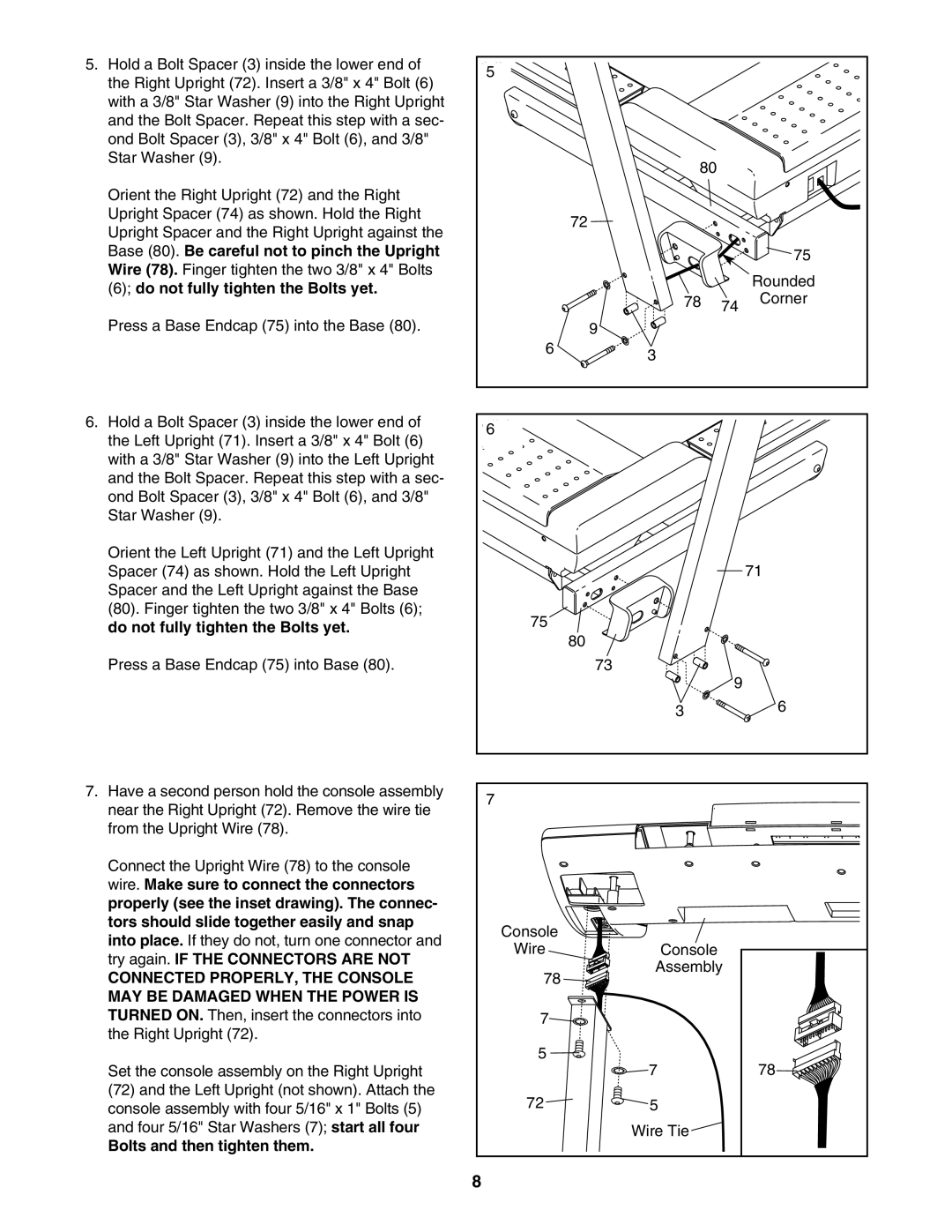
5. Hold a Bolt Spacer (3) inside the lower end of | 5 |
|
|
|
the Right Upright (72). Insert a 3/8" x 4" Bolt (6) |
|
|
| |
|
|
|
| |
with a 3/8" Star Washer (9) into the Right Upright |
|
|
|
|
and the Bolt Spacer. Repeat this step with a sec- |
|
|
|
|
ond Bolt Spacer (3), 3/8" x 4" Bolt (6), and 3/8" |
|
|
|
|
Star Washer (9). |
| 80 |
|
|
|
|
|
| |
Orient the Right Upright (72) and the Right |
|
|
|
|
Upright Spacer (74) as shown. Hold the Right |
| 72 |
|
|
Upright Spacer and the Right Upright against the |
|
|
| |
|
|
|
| |
Base (80). Be careful not to pinch the Upright |
|
|
| 75 |
Wire (78). Finger tighten the two 3/8" x 4" Bolts |
|
|
| Rounded |
(6); do not fully tighten the Bolts yet. |
|
|
| |
| 78 |
| Corner | |
|
| 74 | ||
|
|
|
| |
Press a Base Endcap (75) into the Base (80). |
| 9 |
|
|
| 6 | 3 |
|
|
|
|
|
| |
6. Hold a Bolt Spacer (3) inside the lower end of | 6 |
|
|
|
the Left Upright (71). Insert a 3/8" x 4" Bolt (6) |
|
|
| |
|
|
|
| |
with a 3/8" Star Washer (9) into the Left Upright |
|
|
|
|
and the Bolt Spacer. Repeat this step with a sec- |
|
|
|
|
ond Bolt Spacer (3), 3/8" x 4" Bolt (6), and 3/8" |
|
|
|
|
Star Washer (9). |
|
|
|
|
Orient the Left Upright (71) and the Left Upright |
|
|
|
|
Spacer (74) as shown. Hold the Left Upright |
|
|
| 71 |
Spacer and the Left Upright against the Base |
|
|
|
|
(80). Finger tighten the two 3/8" x 4" Bolts (6); | 75 |
|
|
|
do not fully tighten the Bolts yet. |
|
|
| |
| 80 |
|
| |
|
|
|
| |
Press a Base Endcap (75) into Base (80). |
| 73 |
|
|
|
|
| 9 |
|
|
| 3 |
| 6 |
|
|
|
| |
7. Have a second person hold the console assembly | 7 |
|
|
|
near the Right Upright (72). Remove the wire tie |
|
|
| |
|
|
|
| |
from the Upright Wire (78). |
|
|
|
|
Connect the Upright Wire (78) to the console |
|
|
|
|
wire. Make sure to connect the connectors |
|
|
|
|
properly (see the inset drawing). The connec- |
|
|
|
|
tors should slide together easily and snap | Console |
|
|
|
into place. If they do not, turn one connector and |
|
|
| |
Wire | Console |
|
| |
try again. IF THE CONNECTORS ARE NOT |
|
| ||
| Assembly |
| ||
CONNECTED PROPERLY, THE CONSOLE | 78 |
| ||
|
|
| ||
MAY BE DAMAGED WHEN THE POWER IS |
|
|
|
|
TURNED ON. Then, insert the connectors into | 7 |
|
|
|
the Right Upright (72). |
|
|
|
|
Set the console assembly on the Right Upright | 5 | 7 |
| 78 |
|
| |||
(72) and the Left Upright (not shown). Attach the | 72 | 5 |
|
|
console assembly with four 5/16" x 1" Bolts (5) |
|
| ||
and four 5/16" Star Washers (7); start all four |
| Wire Tie |
|
|
Bolts and then tighten them. |
|
|
|
|
| 8 |
|
|
|