5-9 Connector Definitions
Primary ATX Power
Connector
The main power supply connector on the
Processor Power Connector
The header at JPW2 must also be connected to the power supply to provide power for the processor(s). See the table on the right for pin defi nitions.
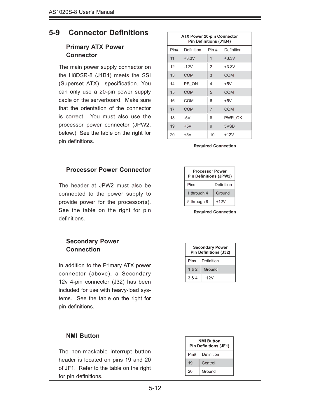
ATX Power
Pin Definitions (J1B4)
Pin# | Defi nition | Pin # | Defi nition | |
11 | +3.3V | 1 | +3.3V | |
12 |
| +3.3V | ||
2 | ||||
13 | COM |
| COM | |
3 | ||||
14 | PS_ON |
| +5V | |
4 | ||||
15 | COM |
| COM | |
5 | ||||
16 | COM |
| +5V | |
6 | ||||
17 | COM |
| COM | |
7 | ||||
18 |
| PWR_OK | ||
8 | ||||
19 | +5V | 9 | 5VSB | |
20 | +5V | 10 | +12V | |
|
|
|
|
Required Connection
Processor Power
Pin Definitions (JPW2)
Pins | Defi nition | |
1 through 4 | Ground | |
5 through 8 | +12V | |
|
|
Required Connection
Secondary Power
Connection
In addition to the Primary ATX power connector (above), a Secondary 12v
Secondary Power
Pin Definitions (J32)
Pins | Defi nition | |
1 & 2 | Ground | |
3 & 4 | +12V | |
|
|
NMI Button
The
NMI Button
Pin Definitions (JF1)
Pin# Defi nition
19Control
20Ground