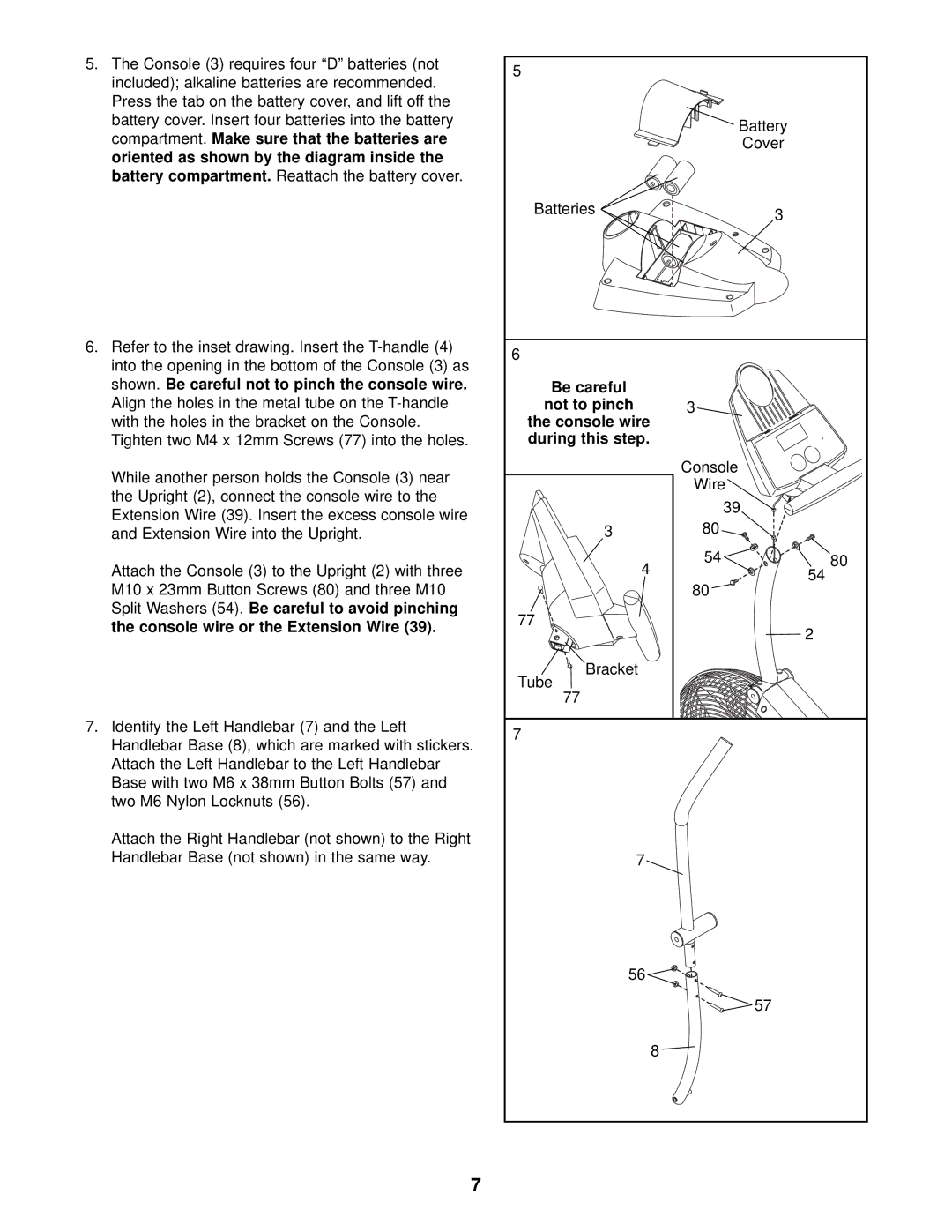
5.The Console (3) requires four “D” batteries (not included); alkaline batteries are recommended. Press the tab on the battery cover, and lift off the battery cover. Insert four batteries into the battery compartment. Make sure that the batteries are oriented as shown by the diagram inside the battery compartment. Reattach the battery cover.
6.Refer to the inset drawing. Insert the
While another person holds the Console (3) near the Upright (2), connect the console wire to the Extension Wire (39). Insert the excess console wire and Extension Wire into the Upright.
Attach the Console (3) to the Upright (2) with three M10 x 23mm Button Screws (80) and three M10 Split Washers (54). Be careful to avoid pinching the console wire or the Extension Wire (39).
7.Identify the Left Handlebar (7) and the Left Handlebar Base (8), which are marked with stickers. Attach the Left Handlebar to the Left Handlebar Base with two M6 x 38mm Button Bolts (57) and two M6 Nylon Locknuts (56).
Attach the Right Handlebar (not shown) to the Right Handlebar Base (not shown) in the same way.
5 |
|
|
| Battery |
|
| Cover |
|
Batteries | 3 |
|
|
| |
6 |
|
|
Be careful |
|
|
not to pinch | 3 |
|
the console wire |
|
|
during this step. |
|
|
| Console |
|
| Wire |
|
| 39 |
|
3 | 80 |
|
4 | 54 | 80 |
| 54 | |
| 80 | |
|
| |
77 |
| 2 |
|
| |
Bracket |
|
|
Tube |
|
|
77 |
|
|
7 |
|
|
7 |
|
|
56 |
|
|
| 57 |
|
| 8 |
|
7