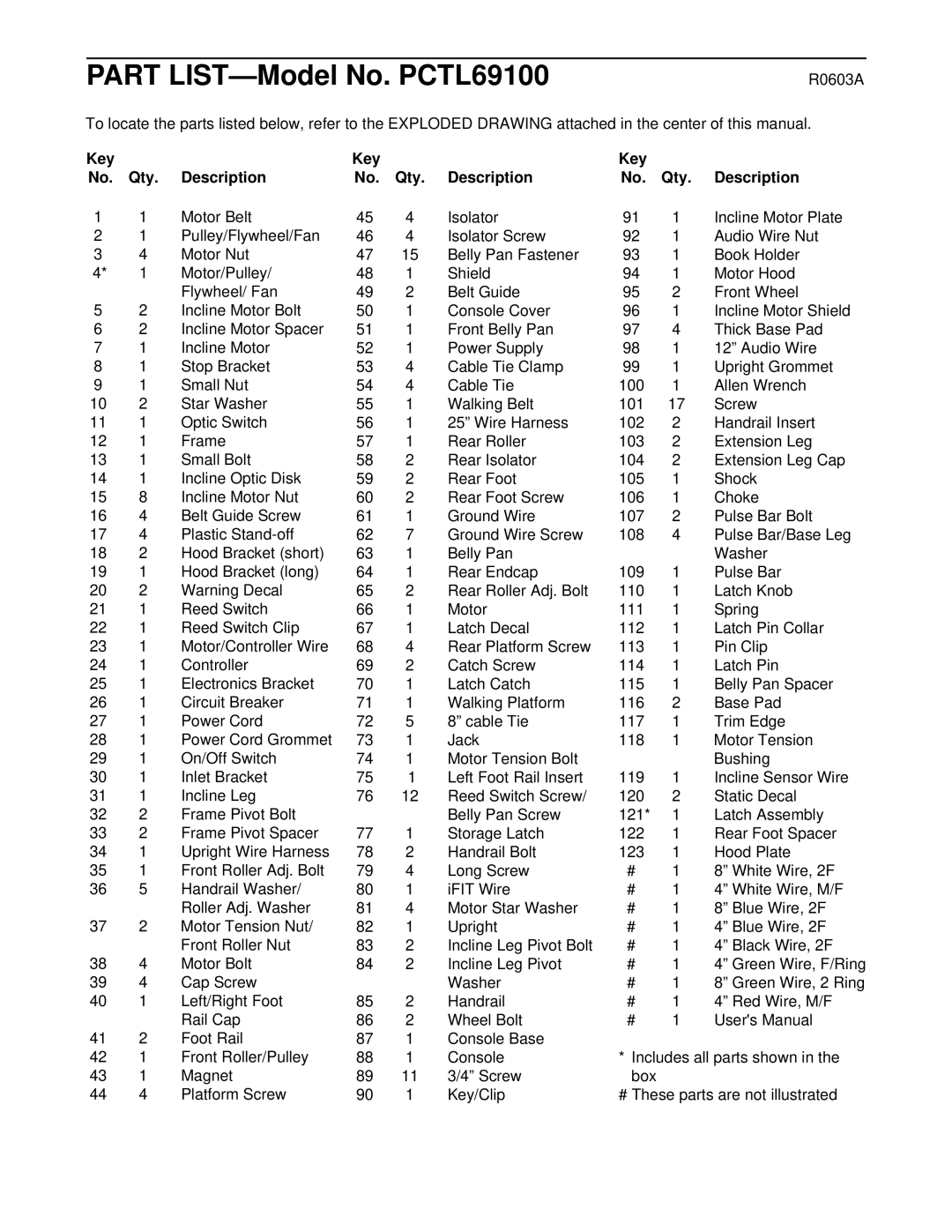
PART LIST—Model No. PCTL69100
To locate the parts listed below, refer to the EXPLODED DRAWING attached in the center of this manual.
Key |
|
| Key |
|
|
No. | Qty. | Description | No. | Qty. | Description |
1 | 1 | Motor Belt | 45 | 4 | Isolator |
2 | 1 | Pulley/Flywheel/Fan | 46 | 4 | Isolator Screw |
3 | 4 | Motor Nut | 47 | 15 | Belly Pan Fastener |
4* | 1 | Motor/Pulley/ | 48 | 1 | Shield |
|
| Flywheel/ Fan | 49 | 2 | Belt Guide |
5 | 2 | Incline Motor Bolt | 50 | 1 | Console Cover |
6 | 2 | Incline Motor Spacer | 51 | 1 | Front Belly Pan |
7 | 1 | Incline Motor | 52 | 1 | Power Supply |
8 | 1 | Stop Bracket | 53 | 4 | Cable Tie Clamp |
9 | 1 | Small Nut | 54 | 4 | Cable Tie |
10 | 2 | Star Washer | 55 | 1 | Walking Belt |
11 | 1 | Optic Switch | 56 | 1 | 25” Wire Harness |
12 | 1 | Frame | 57 | 1 | Rear Roller |
13 | 1 | Small Bolt | 58 | 2 | Rear Isolator |
14 | 1 | Incline Optic Disk | 59 | 2 | Rear Foot |
15 | 8 | Incline Motor Nut | 60 | 2 | Rear Foot Screw |
16 | 4 | Belt Guide Screw | 61 | 1 | Ground Wire |
17 | 4 | Plastic | 62 | 7 | Ground Wire Screw |
18 | 2 | Hood Bracket (short) | 63 | 1 | Belly Pan |
19 | 1 | Hood Bracket (long) | 64 | 1 | Rear Endcap |
20 | 2 | Warning Decal | 65 | 2 | Rear Roller Adj. Bolt |
21 | 1 | Reed Switch | 66 | 1 | Motor |
22 | 1 | Reed Switch Clip | 67 | 1 | Latch Decal |
23 | 1 | Motor/Controller Wire | 68 | 4 | Rear Platform Screw |
24 | 1 | Controller | 69 | 2 | Catch Screw |
25 | 1 | Electronics Bracket | 70 | 1 | Latch Catch |
26 | 1 | Circuit Breaker | 71 | 1 | Walking Platform |
27 | 1 | Power Cord | 72 | 5 | 8” cable Tie |
28 | 1 | Power Cord Grommet | 73 | 1 | Jack |
29 | 1 | On/Off Switch | 74 | 1 | Motor Tension Bolt |
30 | 1 | Inlet Bracket | 75 | 1 | Left Foot Rail Insert |
31 | 1 | Incline Leg | 76 | 12 | Reed Switch Screw/ |
32 | 2 | Frame Pivot Bolt |
|
| Belly Pan Screw |
33 | 2 | Frame Pivot Spacer | 77 | 1 | Storage Latch |
34 | 1 | Upright Wire Harness | 78 | 2 | Handrail Bolt |
35 | 1 | Front Roller Adj. Bolt | 79 | 4 | Long Screw |
36 | 5 | Handrail Washer/ | 80 | 1 | iFIT Wire |
|
| Roller Adj. Washer | 81 | 4 | Motor Star Washer |
37 | 2 | Motor Tension Nut/ | 82 | 1 | Upright |
|
| Front Roller Nut | 83 | 2 | Incline Leg Pivot Bolt |
38 | 4 | Motor Bolt | 84 | 2 | Incline Leg Pivot |
39 | 4 | Cap Screw |
|
| Washer |
40 | 1 | Left/Right Foot | 85 | 2 | Handrail |
|
| Rail Cap | 86 | 2 | Wheel Bolt |
41 | 2 | Foot Rail | 87 | 1 | Console Base |
42 | 1 | Front Roller/Pulley | 88 | 1 | Console |
43 | 1 | Magnet | 89 | 11 | 3/4” Screw |
44 | 4 | Platform Screw | 90 | 1 | Key/Clip |
R0603A
Key
No. Qty. Description
911 Incline Motor Plate
921 Audio Wire Nut
931 Book Holder
941 Motor Hood
952 Front Wheel
961 Incline Motor Shield
974 Thick Base Pad
981 12” Audio Wire
991 Upright Grommet
1001 Allen Wrench
10117 Screw
1022 Handrail Insert
1032 Extension Leg
1042 Extension Leg Cap
1051 Shock
1061 Choke
1072 Pulse Bar Bolt
1084 Pulse Bar/Base Leg Washer
109 | 1 | Pulse Bar |
1101 Latch Knob
1111 Spring
1121 Latch Pin Collar
1131 Pin Clip
114 | 1 | Latch Pin |
115 | 1 | Belly Pan Spacer |
116 | 2 | Base Pad |
1171 Trim Edge
1181 Motor Tension Bushing
1191 Incline Sensor Wire
1202 Static Decal
121* 1 | Latch Assembly |
1221 Rear Foot Spacer
1231 Hood Plate
#1 8” White Wire, 2F
#1 4” White Wire, M/F
#1 8” Blue Wire, 2F
#1 4” Blue Wire, 2F
#1 4” Black Wire, 2F
#1 4” Green Wire, F/Ring
#1 8” Green Wire, 2 Ring
#1 4” Red Wire, M/F
#1 User's Manual
*Includes all parts shown in the box
# These parts are not illustrated
