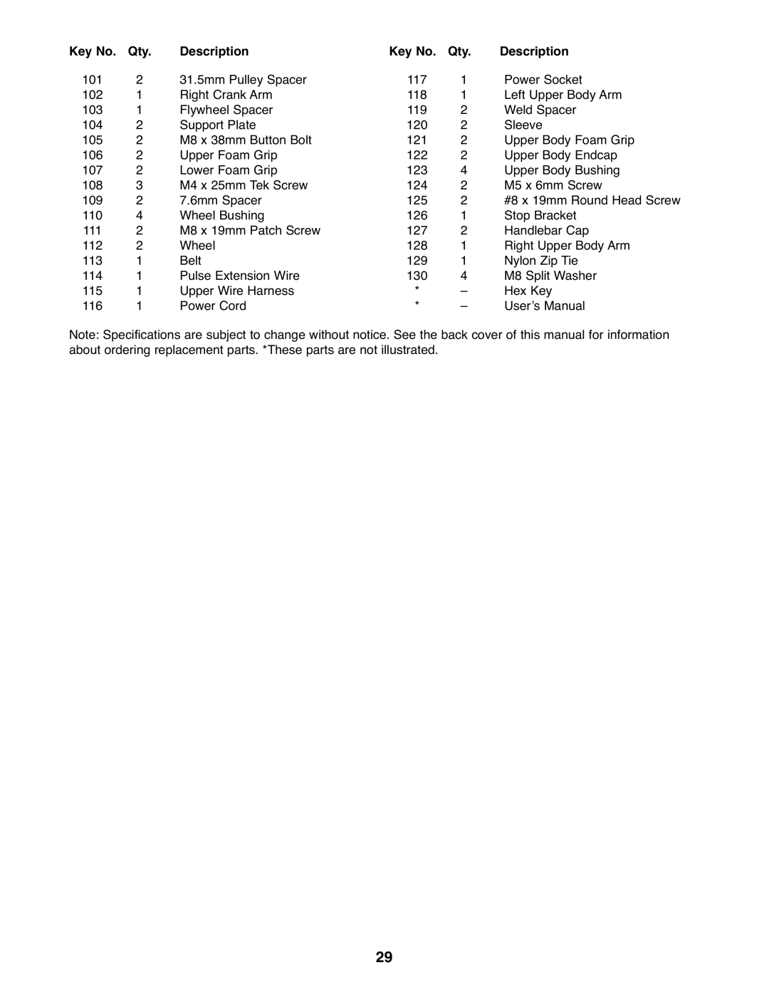
Key No. | Qty. | Description | Key No. | Qty. | Description |
101 | 2 | 31.5mm Pulley Spacer | 117 | 1 | Power Socket |
102 | 1 | Right Crank Arm | 118 | 1 | Left Upper Body Arm |
103 | 1 | Flywheel Spacer | 119 | 2 | Weld Spacer |
104 | 2 | Support Plate | 120 | 2 | Sleeve |
105 | 2 | M8 x 38mm Button Bolt | 121 | 2 | Upper Body Foam Grip |
106 | 2 | Upper Foam Grip | 122 | 2 | Upper Body Endcap |
107 | 2 | Lower Foam Grip | 123 | 4 | Upper Body Bushing |
108 | 3 | M4 x 25mm Tek Screw | 124 | 2 | M5 x 6mm Screw |
109 | 2 | 7.6mm Spacer | 125 | 2 | #8 x 19mm Round Head Screw |
110 | 4 | Wheel Bushing | 126 | 1 | Stop Bracket |
111 | 2 | M8 x 19mm Patch Screw | 127 | 2 | Handlebar Cap |
112 | 2 | Wheel | 128 | 1 | Right Upper Body Arm |
113 | 1 | Belt | 129 | 1 | Nylon Zip Tie |
114 | 1 | Pulse Extension Wire | 130 | 4 | M8 Split Washer |
115 | 1 | Upper Wire Harness | * | – | Hex Key |
116 | 1 | Power Cord | * | – | User’s Manual |
Note: Specifications are subject to change without notice. See the back cover of this manual for information about ordering replacement parts. *These parts are not illustrated.
29
