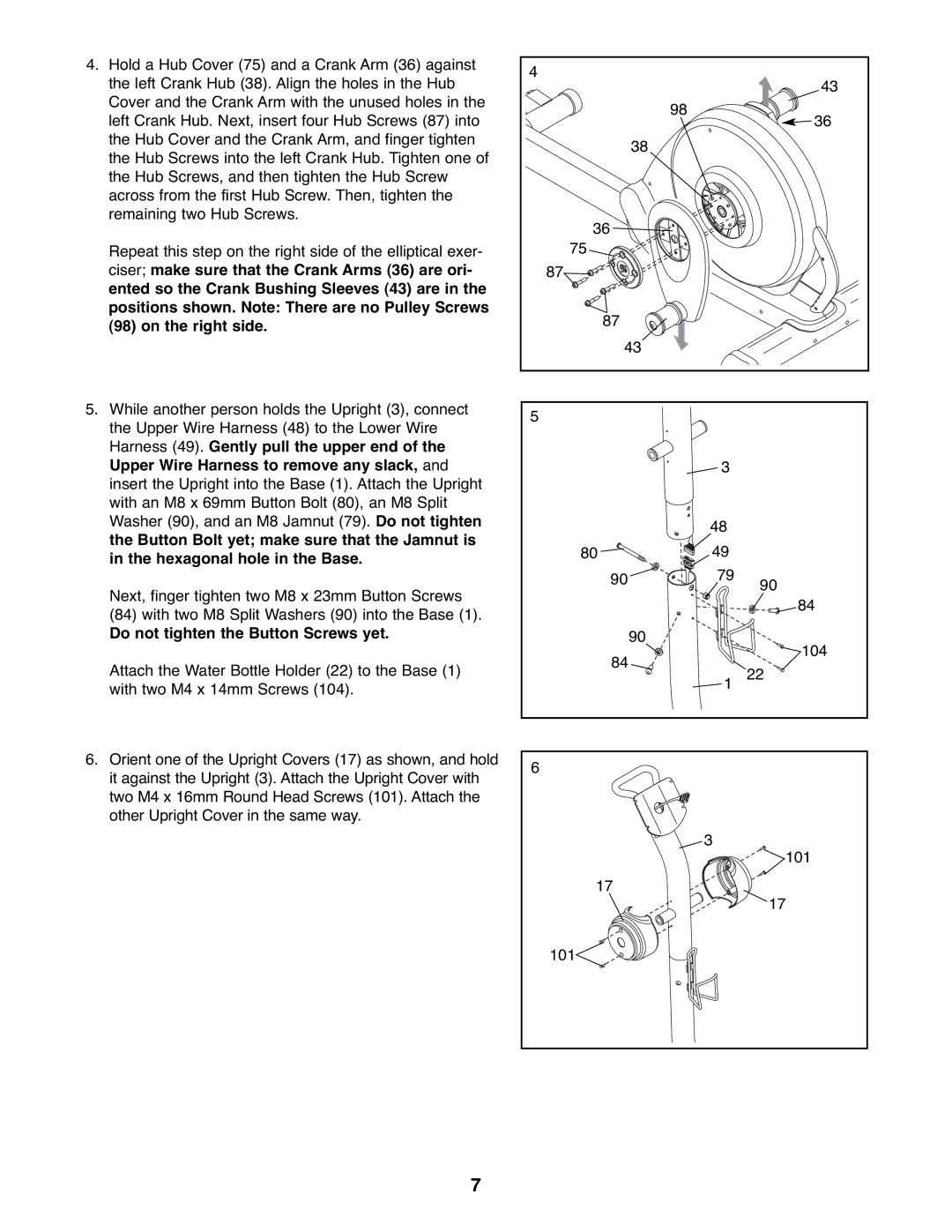
4. Hold a Hub Cover (75) and a Crank Arm (36) against | 4 |
|
|
the left Crank Hub (38). Align the holes in the Hub |
| 43 | |
|
| ||
Cover and the Crank Arm with the unused holes in the |
| 98 |
|
left Crank Hub. Next, insert four Hub Screws (87) into |
| 36 | |
|
| ||
the Hub Cover and the Crank Arm, and finger tighten | 38 |
|
|
the Hub Screws into the left Crank Hub. Tighten one of |
|
| |
|
|
| |
the Hub Screws, and then tighten the Hub Screw |
|
|
|
across from the first Hub Screw. Then, tighten the |
|
|
|
remaining two Hub Screws. | 36 |
|
|
|
|
| |
Repeat this step on the right side of the elliptical exer- | 75 |
|
|
ciser; make sure that the Crank Arms (36) are ori- | 87 |
|
|
ented so the Crank Bushing Sleeves (43) are in the |
|
|
|
positions shown. Note: There are no Pulley Screws | 87 |
|
|
(98) on the right side. |
|
| |
|
|
| |
| 43 |
|
|
5. While another person holds the Upright (3), connect | 5 |
|
|
the Upper Wire Harness (48) to the Lower Wire |
|
| |
|
|
| |
Harness (49). Gently pull the upper end of the |
|
|
|
Upper Wire Harness to remove any slack, and |
| 3 |
|
insert the Upright into the Base (1). Attach the Upright |
|
|
|
with an M8 x 69mm Button Bolt (80), an M8 Split |
|
|
|
Washer (90), and an M8 Jamnut (79). Do not tighten |
| 48 |
|
the Button Bolt yet; make sure that the Jamnut is |
|
| |
80 | 49 |
| |
in the hexagonal hole in the Base. |
| ||
| 79 |
| |
Next, finger tighten two M8 x 23mm Button Screws | 90 | 90 | |
|
| ||
|
| 84 | |
(84) with two M8 Split Washers (90) into the Base (1). |
|
| |
|
|
| |
Do not tighten the Button Screws yet. | 90 |
| 104 |
| 84 |
| |
Attach the Water Bottle Holder (22) to the Base (1) |
| 22 | |
| 1 | ||
with two M4 x 14mm Screws (104). |
| ||
|
|
| |
6. Orient one of the Upright Covers (17) as shown, and hold | 6 |
|
|
it against the Upright (3). Attach the Upright Cover with |
|
| |
|
|
| |
two M4 x 16mm Round Head Screws (101). Attach the |
|
|
|
other Upright Cover in the same way. |
|
|
|
|
| 3 | 101 |
|
|
| |
| 17 |
| 17 |
|
|
| |
| 101 |
|
|
7