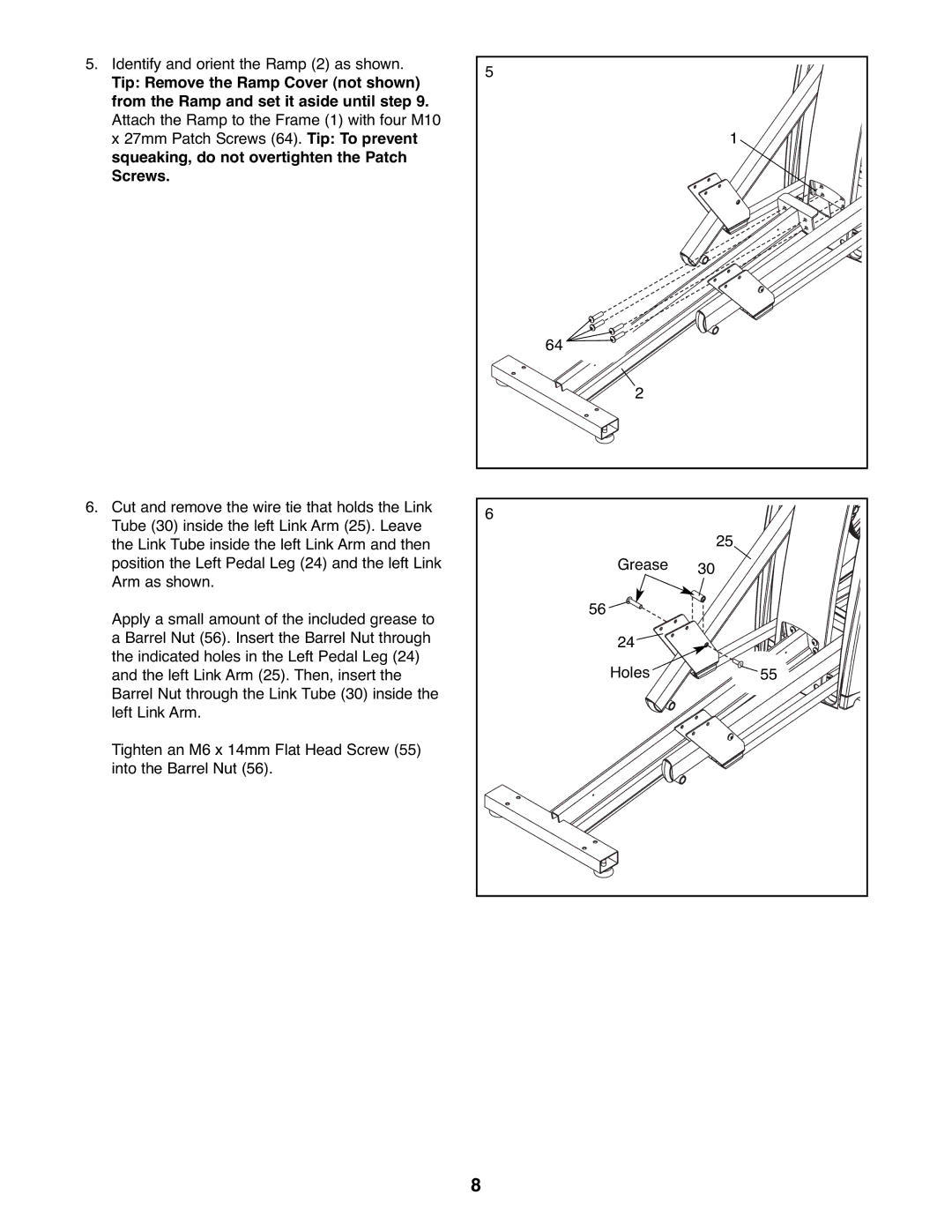
5.Identify and orient the Ramp (2) as shown.
Tip: Remove the Ramp Cover (not shown) from the Ramp and set it aside until step 9. Attach the Ramp to the Frame (1) with four M10 x 27mm Patch Screws (64). Tip: To prevent squeaking, do not overtighten the Patch Screws.
6.Cut and remove the wire tie that holds the Link Tube (30) inside the left Link Arm (25). Leave the Link Tube inside the left Link Arm and then position the Left Pedal Leg (24) and the left Link Arm as shown.
Apply a small amount of the included grease to a Barrel Nut (56). Insert the Barrel Nut through the indicated holes in the Left Pedal Leg (24) and the left Link Arm (25). Then, insert the Barrel Nut through the Link Tube (30) inside the left Link Arm.
Tighten an M6 x 14mm Flat Head Screw (55) into the Barrel Nut (56).
5 |
|
| 1 |
64 |
|
2 |
|
6 |
|
| 25 |
Grease | 30 |
56 |
|
24 |
|
Holes | 55 |
8