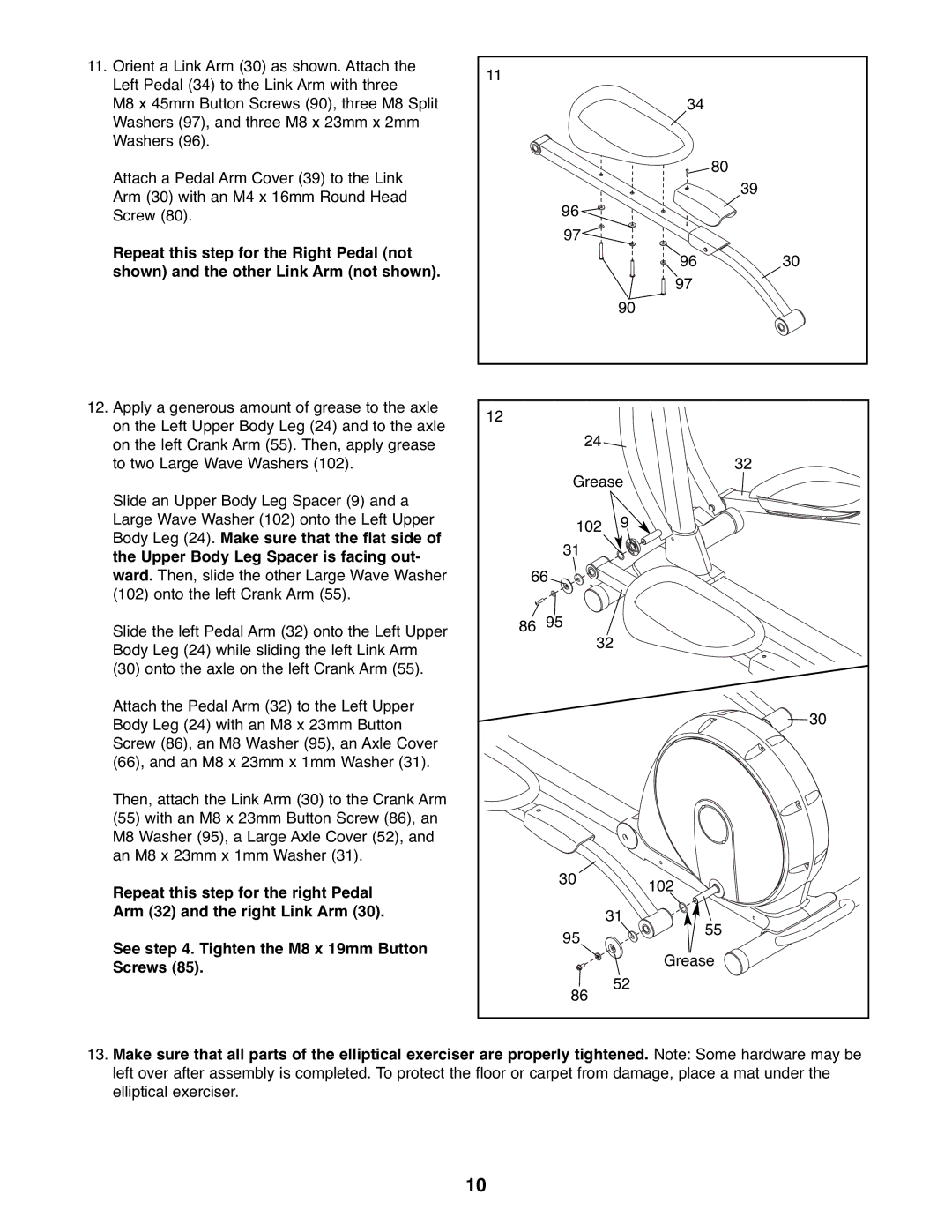
11. | Orient a Link Arm (30) as shown. Attach the | 11 |
|
|
|
| Left Pedal (34) to the Link Arm with three |
|
|
| |
|
|
|
|
| |
| M8 x 45mm Button Screws (90), three M8 Split |
|
| 34 |
|
| Washers (97), and three M8 x 23mm x 2mm |
|
|
|
|
| Washers (96). |
|
|
|
|
| Attach a Pedal Arm Cover (39) to the Link |
|
| 80 |
|
|
|
|
| 39 | |
| Arm (30) with an M4 x 16mm Round Head |
|
|
| |
|
| 96 |
|
| |
| Screw (80). |
|
|
| |
|
|
|
|
| |
| Repeat this step for the Right Pedal (not |
| 97 |
|
|
|
|
| 96 | 30 | |
| shown) and the other Link Arm (not shown). |
|
| ||
|
|
| 97 |
| |
|
|
|
|
| |
|
|
|
| 90 |
|
12. | Apply a generous amount of grease to the axle | 12 |
|
|
|
| on the Left Upper Body Leg (24) and to the axle |
|
|
| |
|
| 24 |
|
| |
| on the left Crank Arm (55). Then, apply grease |
|
|
| |
| to two Large Wave Washers (102). |
| Grease | 32 | |
|
|
|
| ||
| Slide an Upper Body Leg Spacer (9) and a |
|
|
|
|
| Large Wave Washer (102) onto the Left Upper |
| 102 | 9 |
|
| Body Leg (24). Make sure that the flat side of |
| 31 |
|
|
| the Upper Body Leg Spacer is facing out- |
|
|
| |
|
|
|
|
| |
| ward. Then, slide the other Large Wave Washer | 66 |
|
| |
| (102) onto the left Crank Arm (55). |
|
|
|
|
| Slide the left Pedal Arm (32) onto the Left Upper | 86 | 95 |
|
|
|
| 32 |
| ||
| Body Leg (24) while sliding the left Link Arm |
|
| ||
|
|
|
|
| |
| (30) onto the axle on the left Crank Arm (55). |
|
|
|
|
| Attach the Pedal Arm (32) to the Left Upper |
|
|
| 30 |
| Body Leg (24) with an M8 x 23mm Button |
|
|
| |
|
|
|
|
| |
| Screw (86), an M8 Washer (95), an Axle Cover |
|
|
|
|
| (66), and an M8 x 23mm x 1mm Washer (31). |
|
|
|
|
| Then, attach the Link Arm (30) to the Crank Arm |
|
|
|
|
| (55) with an M8 x 23mm Button Screw (86), an |
|
|
|
|
| M8 Washer (95), a Large Axle Cover (52), and |
|
|
|
|
| an M8 x 23mm x 1mm Washer (31). |
|
|
|
|
| Repeat this step for the right Pedal |
| 30 | 102 |
|
|
|
|
| ||
|
|
|
|
| |
| Arm (32) and the right Link Arm (30). |
|
| 31 |
|
|
|
| 95 | 55 |
|
| See step 4. Tighten the M8 x 19mm Button |
|
|
| |
|
|
| Grease |
| |
| Screws (85). |
|
|
| |
|
|
| 52 |
| |
|
|
| 86 |
| |
|
|
|
|
| |
13.Make sure that all parts of the elliptical exerciser are properly tightened. Note: Some hardware may be left over after assembly is completed. To protect the floor or carpet from damage, place a mat under the elliptical exerciser.
10