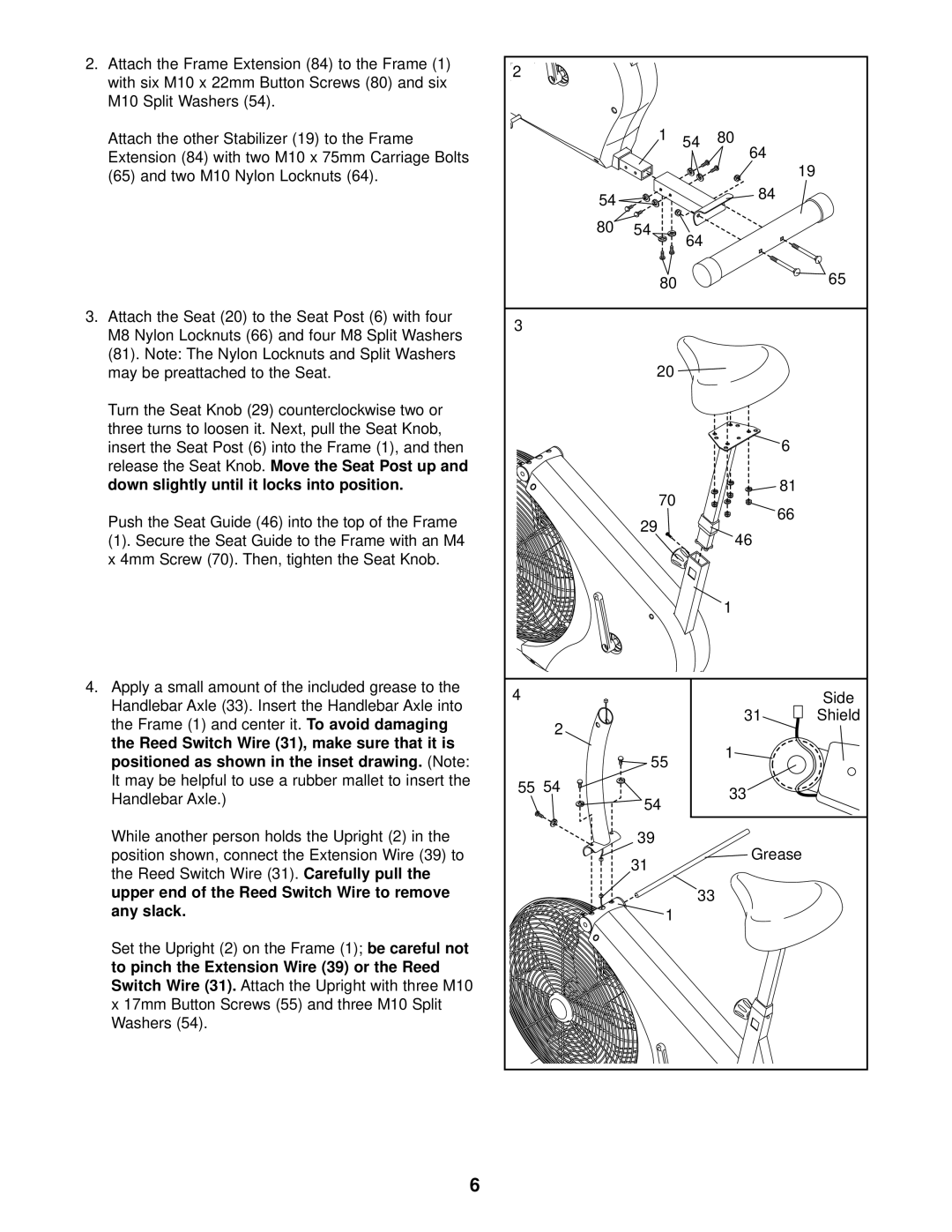
2.Attach the Frame Extension (84) to the Frame (1) with six M10 x 22mm Button Screws (80) and six M10 Split Washers (54).
Attach the other Stabilizer (19) to the Frame Extension (84) with two M10 x 75mm Carriage Bolts (65) and two M10 Nylon Locknuts (64).
3.Attach the Seat (20) to the Seat Post (6) with four M8 Nylon Locknuts (66) and four M8 Split Washers (81). Note: The Nylon Locknuts and Split Washers may be preattached to the Seat.
Turn the Seat Knob (29) counterclockwise two or three turns to loosen it. Next, pull the Seat Knob, insert the Seat Post (6) into the Frame (1), and then
release the Seat Knob. Move the Seat Post up and down slightly until it locks into position.
Push the Seat Guide (46) into the top of the Frame
(1). Secure the Seat Guide to the Frame with an M4 x 4mm Screw (70). Then, tighten the Seat Knob.
4.Apply a small amount of the included grease to the Handlebar Axle (33). Insert the Handlebar Axle into
the Frame (1) and center it. | To | avoid | damaging |
the Reed Switch Wire (31), make sure that it is | |||
positioned as shown in the inset drawing. |
|
| (Note: |
It may be helpful to use a rubber mallet to | insert | the | |
Handlebar Axle.) |
|
|
|
While another person holds the Upright (2) in the position shown, connect the Extension Wire (39) to
the Reed Switch Wire (31). Carefully pull the upper end of the Reed Switch Wire to remove
any slack.
Set the Upright (2) on the Frame (1); | be careful not | |
to pinch the Extension Wire (39) or the Reed |
| |
Switch Wire (31). | Attach the Upright with three M10 | |
x 17mm Button Screws (55) and three M10 Split Washers (54).
2 |
|
|
|
|
|
|
| 1 | 54 | 80 |
|
|
|
|
| 64 |
|
|
|
|
|
| 19 |
| 54 |
|
| 84 |
|
|
|
|
|
| |
| 80 | 54 | 64 |
|
|
|
|
|
|
| |
|
| 80 |
|
| 65 |
3 |
|
|
|
|
|
|
| 20 |
|
|
|
|
|
|
|
| 6 |
|
| 70 |
|
| 81 |
|
|
|
| 66 | |
|
| 29 |
|
| |
|
|
| 46 |
| |
|
|
|
|
| |
|
|
|
| 1 |
|
4 |
|
|
|
| Side |
| 2 |
|
| 31 | Shield |
|
|
|
|
| |
|
| 55 |
| 1 |
|
|
|
|
|
| |
55 | 54 | 54 |
| 33 |
|
|
|
|
| ||
|
|
|
|
| |
|
| 39 |
| Grease |
|
|
| 31 |
|
| |
|
|
|
|
| |
|
|
| 33 |
|
|
|
| 1 |
|
|
|
6
