Reference Manual
Rosemount 1154
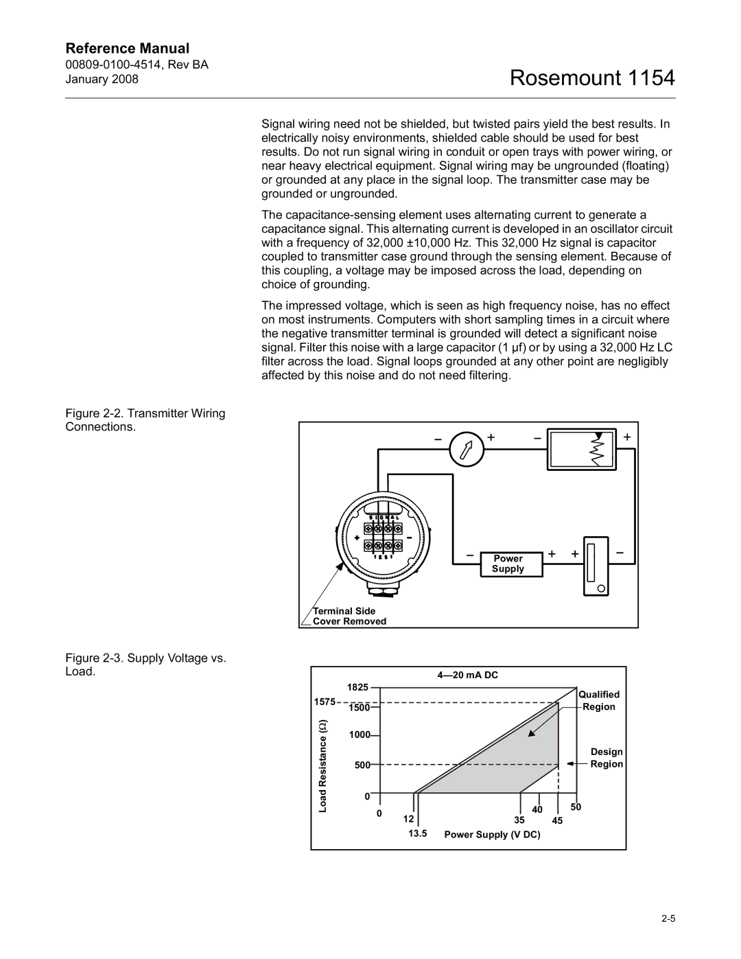
Figure 2-2. Transmitter Wiring Connections.
Figure 2-3. Supply Voltage vs. Load.
Signal wiring need not be shielded, but twisted pairs yield the best results. In electrically noisy environments, shielded cable should be used for best results. Do not run signal wiring in conduit or open trays with power wiring, or near heavy electrical equipment. Signal wiring may be ungrounded (floating) or grounded at any place in the signal loop. The transmitter case may be grounded or ungrounded.
The capacitance-sensing element uses alternating current to generate a capacitance signal. This alternating current is developed in an oscillator circuit with a frequency of 32,000 ±10,000 Hz. This 32,000 Hz signal is capacitor coupled to transmitter case ground through the sensing element. Because of this coupling, a voltage may be imposed across the load, depending on choice of grounding.
The impressed voltage, which is seen as high frequency noise, has no effect on most instruments. Computers with short sampling times in a circuit where the negative transmitter terminal is grounded will detect a significant noise signal. Filter this noise with a large capacitor (1 µf) or by using a 32,000 Hz LC filter across the load. Signal loops grounded at any other point are negligibly affected by this noise and do not need filtering.
Power |
Supply |
Terminal Side |
Cover Removed |
| 1825 |
|
| Qualified |
1575 |
|
|
| |
1500 |
|
| Region | |
|
|
| ||
(Ω) | 1000 |
|
|
|
Resistance |
|
|
| |
|
|
| Design | |
500 |
|
| Region | |
|
|
|
| |
Load | 0 |
|
|
|
0 |
| 40 | 50 | |
| 12 | 35 | 45 | |
|
|
13.5Power Supply (V DC)