Rosemount 1154
Reference Manual
SAFETY MESSAGES
Instructions and procedures in this section may require special precautions to ensure the safety of the people performing the operations. Information that raises potential safety issues is indicated by a warning message. The following warning messages appear in this section.
Use only the procedures and new parts specifically referenced in this manual to ensure specification performance and certification compliance. Unauthorized procedures or parts can render the instrument dangerous to life, limb, or property.
Process
TEST TERMINALS
BOARD CHECKOUT
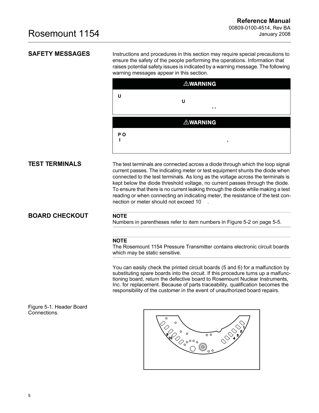
Figure 5-1. Header Board Connections.
The test terminals are connected across a diode through which the loop signal current passes. The indicating meter or test equipment shunts the diode when connected to the test terminals. As long as the voltage across the terminals is kept below the diode threshold voltage, no current passes through the diode. To ensure that there is no current leaking through the diode while making a test reading or when connecting an indicating meter, the resistance of the test con- nection or meter should not exceed 10 Ω.
NOTE
Numbers in parentheses refer to item numbers in Figure 5-2 on page 5-5.
NOTE
The Rosemount 1154 Pressure Transmitter contains electronic circuit boards which may be static sensitive.
You can easily check the printed circuit boards (5 and 6) for a malfunction by substituting spare boards into the circuit. If this procedure turns up a malfunc- tioning board, return the defective board to Rosemount Nuclear Instruments, Inc. for replacement. Because of parts traceability, qualification becomes the responsibility of the customer in the event of unauthorized board repairs.
COMPONENT SIDE UP |
