Reference Manual
Rosemount 1154
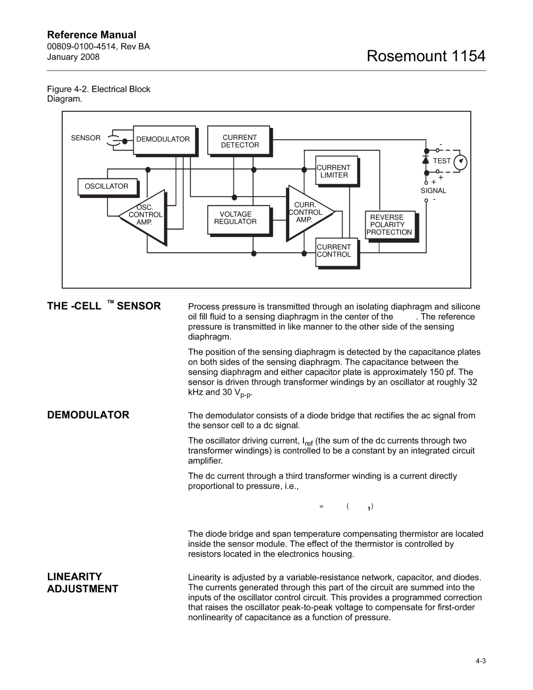
Figure 4-2. Electrical Block
Diagram.
SENSOR | DEMODULATOR | CURRENT |
|
| - |
|
| DETECTOR |
|
| |
|
|
|
| TEST | |
|
|
| CURRENT |
| + |
|
|
| LIMITER | + | |
OSCILLATOR |
|
| |||
|
| SIGNAL | |||
|
|
|
| ||
|
|
| CURR. | - |
|
| OSC. |
|
|
| |
|
| CONTROL |
|
| |
| CONTROL | VOLTAGE | REVERSE |
| |
| AMP. |
| |||
| AMP. | REGULATOR |
| ||
| POLARITY |
| |||
|
|
| |||
|
|
|
|
| |
|
|
|
| PROTECTION |
|
|
|
| CURRENT |
|
|
|
|
| CONTROL |
|
|
THE
The position of the sensing diaphragm is detected by the capacitance plates on both sides of the sensing diaphragm. The capacitance between the sensing diaphragm and either capacitor plate is approximately 150 pf. The sensor is driven through transformer windings by an oscillator at roughly 32 kHz and 30
DEMODULATOR | The demodulator consists of a diode bridge that rectifies the ac signal from |
| the sensor cell to a dc signal. |
The oscillator driving current, Iref (the sum of the dc currents through two transformer windings) is controlled to be a constant by an integrated circuit amplifier.
The dc current through a third transformer winding is a current directly proportional to pressure, i.e.,
Idiff = fVp –
LINEARITY ADJUSTMENT
The diode bridge and span temperature compensating thermistor are located inside the sensor module. The effect of the thermistor is controlled by resistors located in the electronics housing.
Linearity is adjusted by a
