| Reference Manual |
Rosemount 1154 | |
January 2008 | |
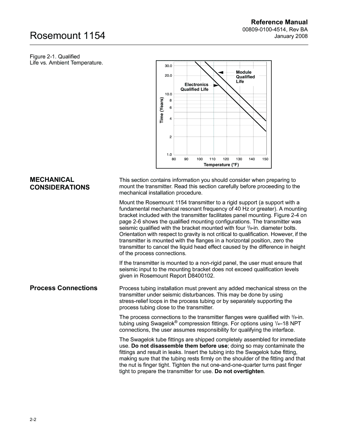
Figure |
|
Life vs. Ambient Temperature. |
|
| Module |
| Qualified |
| Life |
| Electronics |
| Qualified Life |
| Time (Years) |
| Temperature (°F) |
MECHANICAL CONSIDERATIONS
Process Connections
This section contains information you should consider when preparing to mount the transmitter. Read this section carefully before proceeding to the mechanical installation procedure.
Mount the Rosemount 1154 transmitter to a rigid support (a support with a fundamental mechanical resonant frequency of 40 Hz or greater). A mounting bracket included with the transmitter facilitates panel mounting. Figure
If the transmitter is mounted to a
Process tubing installation must prevent any added mechanical stress on the transmitter under seismic disturbances. This may be done by using
The process connections to the transmitter flanges were qualified with
The Swagelok tube fittings are shipped completely assembled for immediate use. Do not disassemble them before use; doing so may contaminate the fittings and result in leaks. Insert the tubing into the Swagelok tube fitting, making sure that the tubing rests firmly on the shoulder of the fitting and that the nut is finger tight. Tighten the nut
