Rosemount 1154
Reference Manual
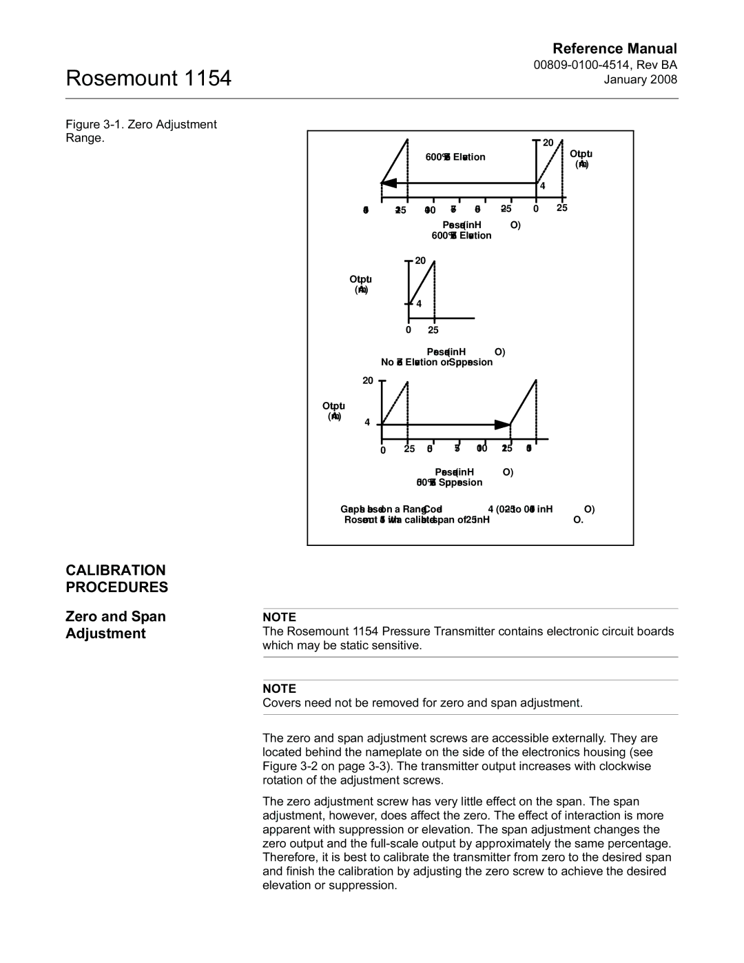
Figure 3-1. Zero Adjustment Range.
|
|
|
|
|
| 20 |
|
| 600% Zero Elevation |
| Output | ||
|
|
| (mA) | |||
|
|
|
|
|
| |
|
|
|
|
|
| 4 |
0 | 25 | |||||
Pressure (inH2O)
600% Zero Elevation➀
![]()
![]() 20
20
Output (mA)
![]()
![]() 4
4
0 25
Pressure (inH2O)
No Zero Elevation or Suppression➀
| 20 |
|
|
|
|
|
|
Output |
|
|
|
|
|
|
|
(mA) | 4 |
|
|
|
|
|
|
|
|
|
|
|
|
| |
| 0 | 25 | 50 | 75 | 100 | 125 | 150 |
Pressure (inH2O)
500% Zero Suppression➀
➀Graphs based on a Range Code 4
CALIBRATION PROCEDURES
Zero and Span Adjustment
NOTE
The Rosemount 1154 Pressure Transmitter contains electronic circuit boards which may be static sensitive.
NOTE
Covers need not be removed for zero and span adjustment.
The zero and span adjustment screws are accessible externally. They are located behind the nameplate on the side of the electronics housing (see Figure
The zero adjustment screw has very little effect on the span. The span adjustment, however, does affect the zero. The effect of interaction is more apparent with suppression or elevation. The span adjustment changes the zero output and the