Rosemount 1154
Reference Manual
Conduit
1.Seal the conduit threads with thread sealant. (The transmitter conduit seal interface was qualified using Grafoil™ tape.) Conduit threads mate with a standard
2.Starting at zero thread engagement, install the conduit into the transmitter between 4 and 7 turns, or a minimum of 12.5
3.Provide separate support for the conduit if necessary.
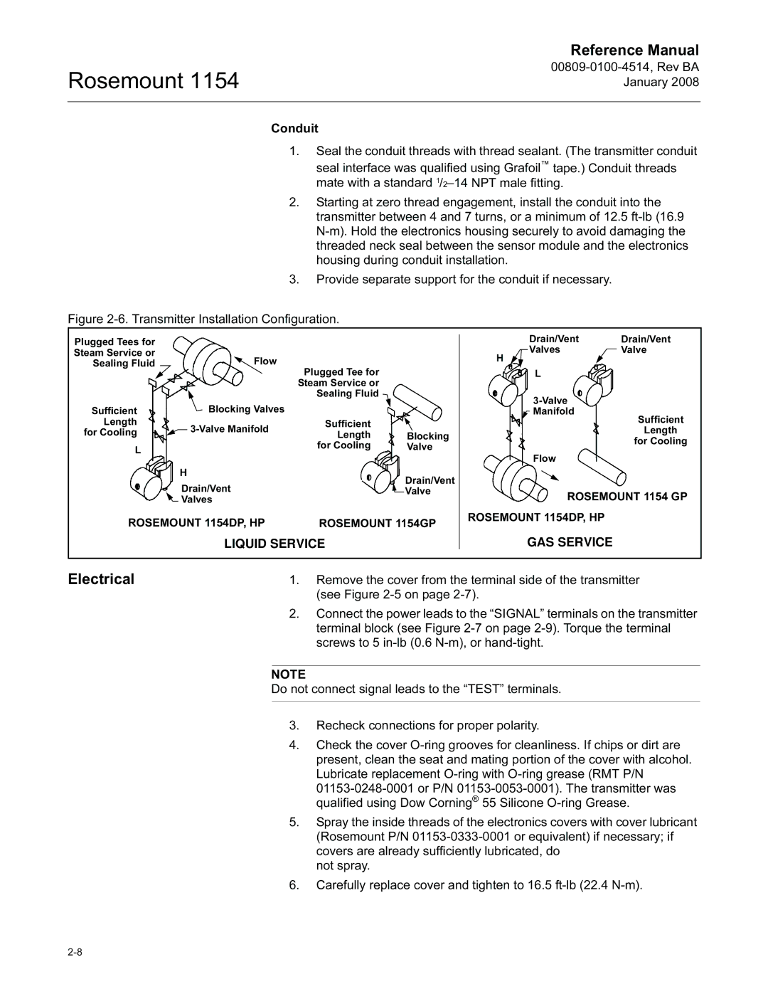
Figure 2-6. Transmitter Installation Configuration.
Plugged Tees for |
|
Steam Service or | Flow |
Sealing Fluid |
|
| Plugged Tee for |
| |
|
| Steam Service or |
| |
|
| Sealing Fluid |
| |
Sufficient | Blocking Valves |
|
| |
Length | Sufficient |
| ||
for Cooling |
| |||
Length | Blocking | |||
| ||||
|
| |||
L |
| for Cooling | Valve | |
|
|
| ||
| H |
| Drain/Vent | |
| Drain/Vent |
| ||
|
| Valve | ||
| Valves |
| ||
|
|
| ||
ROSEMOUNT 1154DP, HP | ROSEMOUNT 1154GP | |||
LIQUID SERVICE
Drain/Vent | Drain/Vent |
Valves | Valve |
H |
|
L |
|
![]()
![]() Manifold
Manifold
Sufficient
Length
for Cooling
Flow
ROSEMOUNT 1154 GP
ROSEMOUNT 1154DP, HP
GAS SERVICE
Electrical | 1. | Remove the cover from the terminal side of the transmitter | |
|
|
| (see Figure |
| 2. | Connect the power leads to the “SIGNAL” terminals on the transmitter | |
|
|
| terminal block (see Figure |
|
|
| screws to 5 |
|
|
|
|
| NOTE |
| |
| Do not connect signal leads to the “TEST” terminals. | ||
|
|
|
|
| 3. | Recheck connections for proper polarity. | |
| 4. | Check the cover | |
|
|
| present, clean the seat and mating portion of the cover with alcohol. |
|
|
| Lubricate replacement |
|
|
| |
|
|
| qualified using Dow Corning® 55 Silicone |
| 5. | Spray the inside threads of the electronics covers with cover lubricant | |
|
|
| (Rosemount P/N |
|
|
| covers are already sufficiently lubricated, do |
|
|
| not spray. |
| 6. | Carefully replace cover and tighten to 16.5 | |