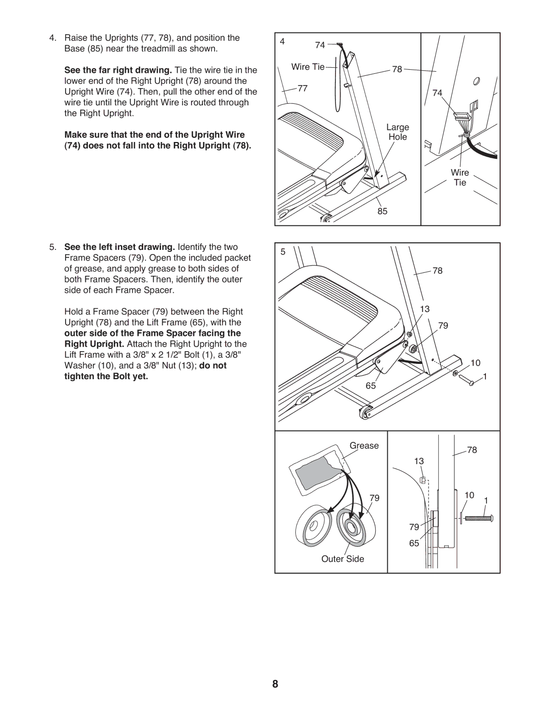
4. Raise the Uprights (77, 78), and position the | 4 | 74 |
|
|
|
Base (85) near the treadmill as shown. | 78 |
|
| ||
See the far right drawing. Tie the wire tie in the |
| Wire Tie |
|
| |
lower end of the Right Upright (78) around the |
| 77 |
|
|
|
Upright Wire (74). Then, pull the other end of the |
|
| 74 |
| |
wire tie until the Upright Wire is routed through |
|
|
|
| |
the Right Upright. |
|
| Large |
|
|
Make sure that the end of the Upright Wire |
|
|
|
| |
|
| Hole |
|
| |
(74) does not fall into the Right Upright (78). |
|
|
| Wire |
|
|
|
|
|
| |
|
| 85 | Tie |
| |
|
|
|
| ||
5. See the left inset drawing. Identify the two | 5 |
|
|
|
|
Frame Spacers (79). Open the included packet |
|
|
|
| |
of grease, and apply grease to both sides of |
|
|
| 78 |
|
both Frame Spacers. Then, identify the outer |
|
|
|
| |
side of each Frame Spacer. |
|
| 13 |
|
|
Hold a Frame Spacer (79) between the Right |
|
|
|
| |
Upright (78) and the Lift Frame (65), with the |
|
|
| 79 |
|
outer side of the Frame Spacer facing the |
|
|
|
| |
Right Upright. Attach the Right Upright to the |
|
|
|
|
|
Lift Frame with a 3/8" x 2 1/2" Bolt (1), a 3/8" |
|
|
| 10 |
|
Washer (10), and a 3/8" Nut (13); do not |
|
|
| 1 | |
tighten the Bolt yet. |
| 65 |
|
| |
|
|
|
|
| |
|
| Grease | 13 | 78 |
|
|
|
|
|
| |
|
| 79 | 79 | 10 | 1 |
|
|
|
|
| |
|
| Outer Side | 65 |
|
|
|
|
|
|
| |
| 8 |
|
|
|
|
