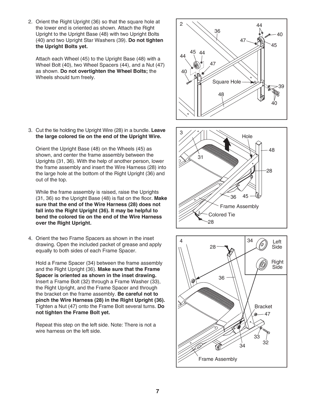
2.Orient the Right Upright (36) so that the square hole at the lower end is oriented as shown. Attach the Right Upright to the Upright Base (48) with two Upright Bolts (40) and two Upright Star Washers (39). Do not tighten the Upright Bolts yet.
Attach each Wheel (45) to the Upright Base (48) with a Wheel Bolt (40), two Wheel Spacers (44), and a Nut (47) as shown. Do not overtighten the Wheel Bolts; the Wheels should turn freely.
3.Cut the tie holding the Upright Wire (28) in a bundle. Leave the large colored tie on the end of the Upright Wire.
Orient the Upright Base (48) on the Wheels (45) as shown, and center the frame assembly between the Uprights (31, 36). With the help of another person, lower the frame assembly and insert the Wire Harness (28) into the large hole at the bottom of the Right Upright (36) and out of the top.
While the frame assembly is raised, raise the Uprights (31, 36) so the Upright Base (48) is flat on the floor. Make sure that the end of the Wire Harness (28) does not fall into the Right Upright (36). It may be helpful to bend the colored tie on the end of the Wire Harness over the Right Upright.
2 | 36 | 44 |
| 40 | |
|
| |
|
| 47 |
|
| 45 |
45 | 44 |
|
44 |
|
|
| 47 |
|
40 |
|
|
| Square Hole | |
|
| 39 |
| 48 |
|
|
| 40 |
3 |
| Hole |
|
| |
|
| 48 |
| 31 |
|
|
| 28 |
| 36 | 45 |
Frame Assembly
![]()
![]() Colored Tie
Colored Tie
![]() 28
28
4.Orient the two Frame Spacers as shown in the inset drawing. Open the included packet of grease and apply equally to both sides of each Frame Spacer.
Hold a Frame Spacer (34) between the frame assembly and the Right Upright (36). Make sure that the Frame
Spacer is oriented as shown in the inset drawing. Insert a Frame Bolt (32) through a Frame Washer (33), the Right Upright, and the Frame Spacer and through the bracket on the frame assembly. Be careful not to pinch the Wire Harness (28) in the Right Upright (36). Tighten a Nut (47) onto the Frame Bolt several turns. Do not tighten the Frame Bolt yet.
Repeat this step on the left side. Note: There is not a wire harness on the left side.
4 | 34 | Left |
| 28 | Side |
|
| Right |
|
| Side |
| 36 |
|
|
| Bracket |
|
| 47 |
|
| 33 |
| 34 | 32 |
|
| |
| Frame Assembly |
|
7