Accelerating the World of Cooking
For further information call
Important Safety Information Please Read First
Table of Contents
Microwave System
Oven Door
Schematics and Schematic Components
Service Parts and Illustrations
Convection Circuit
IR Element and Catalytic Converter
Important Safety Instructions
Grounding Instructions
Installation, Specifications, and Maintenance
Dimensions
Standard Features
Power Supply North America
Construction
Power Supply Europe, Asia-Pacific
Power Supply Latin America
Power Supply South Korea
Built-In Installation Figure
Installation Near Open Heat Source Figure
Setup
Initial Power-up
Oven Restraint Kit TC3-0242 KIT
Stacking
Remove the Lower Access Panel
Remove and Clean the Cooking Surface
Clean Oven Interior
Clean Lower Access Panel Area
Theory of Operation
Chapter
Set Temperature, Cook Cavity Ccsp
Set Temperature, IR Element Irsp and Irsi
Actual Temperature, Cook Cavity TCC
Actual Temperature, IR Element TIR
Fault Code
Keypad
Display
Self-Test Stest
Fault Codes
F2 Cook Temperature Low
F1 Blower Running Status Bad
F3 Magnetron Current Low
F4 Door Monitor Defective
F5 Magnetron Over Temperature
Thermocouple temperature is below the indicated limit
F7 Thermocouple Open
F8 Heat Low
Control System
Mech
VDC Power Supply
Interlock Switches
K1 Mechanical Relay
K2 Mechanical Relay
Faults Screen
Blower Speed Screen
Self-Test Function Screen
Heater Test Screen
Diagnostic Display Screen
Electronic Compartment Temperature Screen
Changing the Cook Chamber Temperature
Cooks Screen
Altering a Recipe
Snooze Mode
Loading a Menu from a Smart Card
Done Screen
Time Screen
Function/Screen
Enter Key Code
Smart Card Reader Cable
Reference page 54 for a schematic of the I/O control board
Board J3 connector Replace I/O control board
Pin connector
If not, correct the voltage supply
VAC is going to the motor controller via pins 2
Troubleshooting
Refer to page 50 for motor controller troubleshooting
Detailed troubleshooting
If high-limit is not tripped, follow the instructions below
Microwave System
Voltage Doubler Circuit Description
Microwave System
Filament and High Voltage Terminals ORG
Magnetron
High-Voltage Transformers
Filament Transformers
F3 Fuse
Wave Guide Cover Replacement
Wiring the High-Voltage Transformers
NGC-3036Kit, Wave Guide Cover Includes Item 31 and sealant
Screws, #8, SST NGC-1047Support, Frame
Remove the wave guide cover. See Wave Guide
Wiring the Filament Transformers
Procedure for Measuring RF Leakage
Testing the High-Voltage Diode
How to Check a Diode
How to Check a Capacitor
How to Check a High-Voltage or Filament Transformer
Magnetron
Components
Remove the top and right side covers
Back and Enter keys, enter the code 9-4-2-8 and press Enter
HV capacitor shorted or failing follow troubleshooting on
Voltage Transformers
Mgtron soft key. Voltage present should be 200 +/- 10%
Unplug the oven and replace relay if necessary
Troubleshooting see F4 Monitor
Primary and secondary, the control would have recorded
Occurrence. See page 25 as well as Oven Door for
Energizing the Microwave System
Oven Door
Oven Door
Critical Adjustment Notes
31 for proper procedure
Oven Burn-In Procedure
Primary and Secondary Interlock Switch Adjustments and Parts
Assembly Notes
PPHD, Cres
5963
Adjusting the Primary Interlock Switch NEW Switch Setup
80 81
DIA
101
98 AR
Critical Adjustment Notes Figure
Refer to Figures 35
Interlock switch status
Actuator and toggle OK Check adjustment and wiring on
New setup for the proper adjustment procedure
Door does not close freely Remove obstructions or readjust
Convection Circuit
Main Convection Heater
Motor Controller Bmsc
High Limit Thermostat
Convection Motor
109 110 113 111
114 105 104 103 102 107
108
106
Replace motor. For access to motor shaft, remove top panel
† Thermostat tripped Reset and determine why the thermostat
Cook Door Open Message Verify which switch is not actuating
Readjust. See pages
Verify motor spins freely
† Motor spins freely Verify motor windings see table below
Disconnect control wiring
Plug on schematics pages 55-63 while incrementing blower
Converter
IR Element
Catalytic Converter
Removing the IR Element
Removing and Installing the Catalytic Converter
Installing a New IR Element
119
122
Schematics and Schematic Components
Wire Harness Replacement P/Ns
Line Voltage Components
Low Voltage Components
Board Schematic
Schematic Tornado NGC
MAG
Schematic Tornado Ngcew
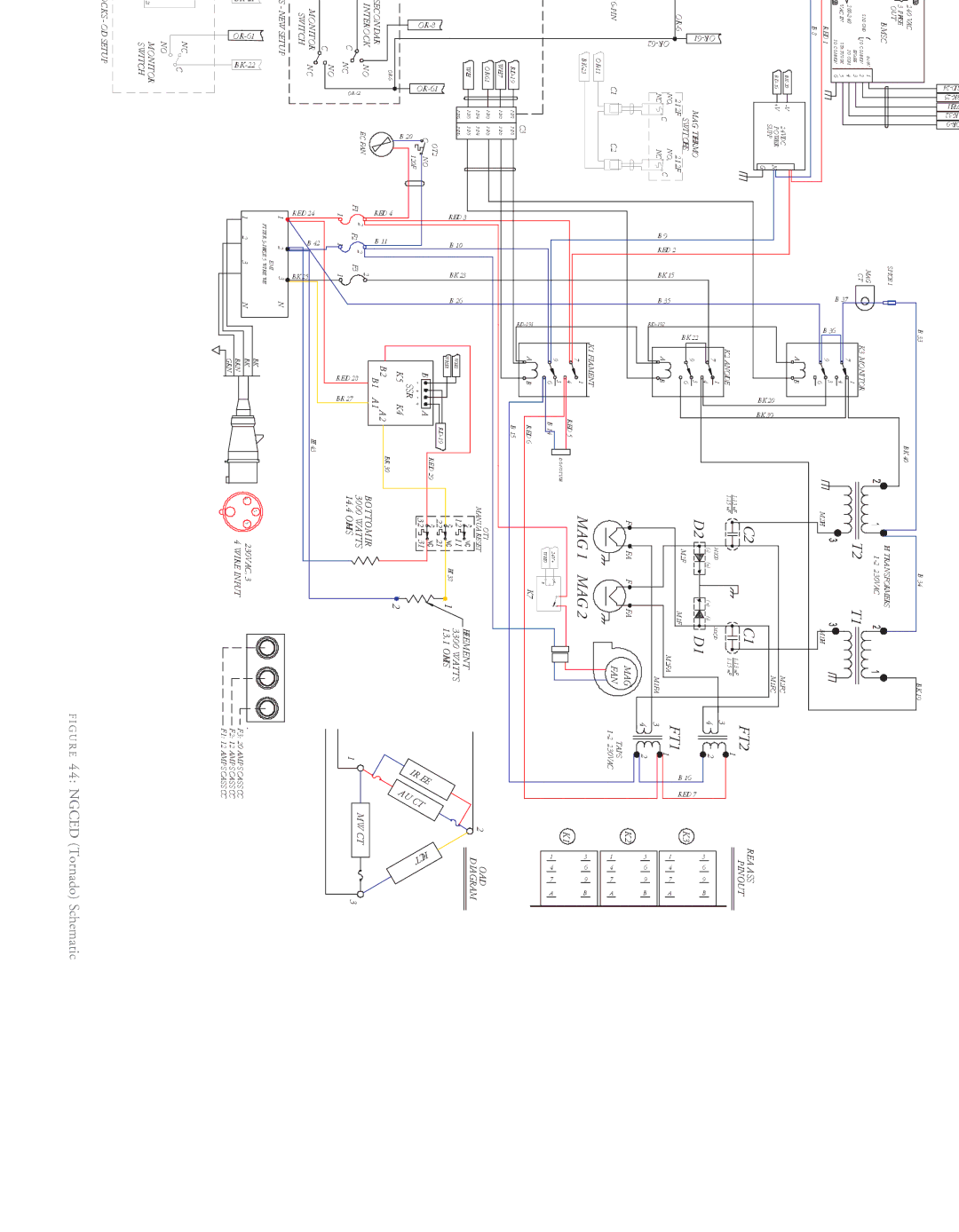
Schematic Tornado Ngced
Schematic Brazil NGC
Service Parts and Illustrations
Control System
Relay
Service Parts and Illustrations
Microwave System
Monitor Circuit Shown in Failsafe State
Microwave System Parts
Wave Guide/Wave Guide Cover Parts
Oven Door
SBK
Primary and Secondary Interlock Switch Parts
Door Switch Parts
Monitor Safety Switch Parts
Primary Safety Switch Parts
80 81 Secondary and Monitor Safety Switch Parts
100
Oven Door Parts
Convection Circuit Block Diagram
Convection Circuit
109 110 113 111 112 Convection Circuit Parts
114 105 104 103 102 107 108 106
Wire Harness Replacement P/N
123 Old Switch Setup 126
IR Element and Catalytic Converter
122 119
129 132 144 139 141
135 137 138 133 134
147 150 162 157 159
153 155 156 151 152
150 Screw, #8-32 x 3/8, Pphd NGC-2011-8
Comprehensive Part List
Comprehensive Part List
Comprehensive Part List
Relay, K7, Magnetron Fan, Standard Europe, Asia-Pacific MPh
Smart Card, Programmed call TurboChef for Part Numbers
800.90T U R B O or