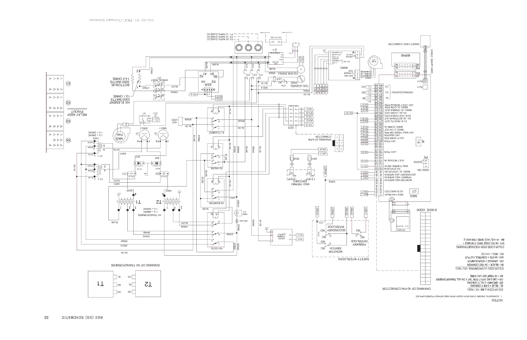
Schematic (Tornado) NGC 41:

E R U G I F

A

7

4

1


K1

B

9

6

3


A

7

4

1


K2

B

9

6

3


PINOUT

A

7

4

1

ASSY RELAY


K3

B

9

6

3


240VAC = 3-1

OHMS 4.14 WATTS 3000 IR BOTTOM

OHMS 1.13 WATTS 3300 ELEMENT HX

2


HT600


OT1


RESET MANUAL


11

12

1

HT520


BL510

21

22


OR540


31

32


K7


J


RELAY_ FAN_MAG


C


B

1-WH


USED


A

+ 24V


NC

NO

NOT


2 MAG


1 MAG

CCCLASS AMPS 12 F1: CC CLASS AMPS 12 F2: CC CLASS AMPS 20 F3:


BL530


BL500

BL300


1

A1


B1


F3

A2


B2

2


K4


K5


SSR


+

-

+

-


A


B


19-RD


301-WH


28-WH


B

A

RD-


191


BR290


6

9

BR230


3


BL160


4

7

BL120


1


FILAMENT K1


BR200 1

F2 2

WIRES BLUE ALL

WIRES OTHER ALL

VIEW OUT-LINE


CONNECTOR CARD SMART


6

COMMON I/O


1


CABLE, SMART


G


5

OK STATUS

IN VAC

2


L2


L2


BK-33

OR-13


4

COM I/O

240-200

3


3

ENABLE


UTINP


MTR


2

COMMON I/O


L

FILTER

L


CMD SPD


BLWR


1

10V-0


BL100

EMI


J6


BMSC


P6

1

BL000


CARD


OUT

1


BR000


BLACK M1


P4


PHASE 3


MODULE VOLTAGE


2


F1


RED M2


VAC 240

3

WHITE M3


J4


2


120°F


4


GREEN


RJ11


BL110


NO

C

BR220


40 40


OT2


(COOLING) FAN1


WH-31


BR210


OR-9

BK-32

BK-25

RD-24


CC

C(+)

CC

RJ11


39 39


)-A(


BR250


EC

38 38

EC

THERMOCOUPLES


C(+)


BL140


37 37


)-A(


IR

36 36

IR


C(+)


35

35


)-A(


34

34


33-BK


IN6P

IN6P


33

33

RTN) MODULE (VOLT 24V-


32-BK


IN5P

IN5P

2-WH


32

32

RTN) (COM (4) BMSC


31-WH

31

31

OUT) (ENABLE (3) BMSC


IN4P

IN4P

29-WH


301-WH


30

30

OUT) (CONV )-(B K4


IN3P

IN3P

61-OR


29 29

OUT) MOD (VOLTS B-K6


27-WH


28-WH

28 28

OUT IR BOTTOM B)-( K5


IN2P

IN2P


27-WH

27 27

OUT) FIL (MAG B-K1


IN1P

IN1P

91-RD


26

26


QC3


25-RD

25

25

(2) COMM BMSC


24-RD

24

24

OUT 10V-0 BMSC


23-BK

23

23

RTN SW THEMO MAG 24V-


A

1 4 7


208VAC = 2-1


2 5 8

K6


TAPS


OR275

3


B

9

3 6


5


BR285

2


4


BL155

1

1 FT


BL155

OR270

3

5


BR280

2

4


BL150

1

2 FT


FAN


MAG

F

FA

F

FA

M1FA


M2FA


M1F


M2F


)-( D1 (+)


(+) D2 )-(


M1CD


M2CD


C1


C2


uF 91.0


uF 91.0

M1FC


M2FC


M1HV


M2HV

BL150

BR260


B

A

RD-

BR500


192

BR400

BL330


6

9

BL335


3


4

7


1


ANODE K2


BL350

BL345


B

A

RD-


193


6

9


3


4

7

BR400


BR240


22-BK


22

22

RTN S&M 24V-


CONNECTOR

4

1


21

21

RTN INTER P 24V-


21-BK


PIN-6 OF DRAWING


20-BK


20

20

IN PS 24V-


1-9


J6


5

2


19-RD

19

19


BL120


18

18


6

3


23-BK


17

17


16-RD

16

16

IN PS +24V


11-OR


15

15


QC2


QC1


14

14


P5


13-OR


13

13

IN MODUAL VOLT


ASPEN


12

12


OR-


11-OR


11

11

IN SW THERMO MAG


10 10

IN STATUS HX


SEL BMSC


C


61


9-OR

9

9

OK) (STATUS (9) BMSC


C

NO


8-OR

8

8

IN INTER (NO) SECONDARY


NO


212°F


212°F


7-OR

7

7

IN INTER (NO) PRIMARY


6


SWITCHES


6-OR


6

IN INTER (NO) MONITOR


5

5


THERMO MAG


4

4


3

3


CT


2-WH

2

2

OUT) (MAG B-K2


1-WH

1

1

RELAY FAN MAG

MAG


T1

T2


240VAC = 3-1


208VAC = 2-1

TRANSFORMERS HV

BL340


BR450


OR440

BR280


OR270


BL150


1


BR410


MONITOR K3


BL355


B

A

CT


MAG

BL370

6

9

1 SPLICE


BR420

OR360

3


5

8

BR420


2


4


BR430 BR260


1

7


VOLTS K6

BR240

BL130

G

N

L

SUPPLY

V-

POWER


24VDC

+V


16-BK

20-RD

OR-61

6-OR

OR-62

NO

NC


NO


NC

OR-8

BK-22

INTERLOCK


SECONDARY


C


C


SWITCH


MONITOR


BK-21

OR-7


NO


C

NC


INTERLOCK

PRIMARY

ODDS EVENS


TRANSFORMERS HV OF DRAWING


BL

OR


T1


BR

BL


T2


OR

BR


INTERLOCKS SAFETY

CONNECTOR PIN-40 OF DRAWING

APPLIED POWER WITHOUT AND OPEN DOOR WITH OVEN SHOWS SCHEMATIC .1

NOTES:

55

SCHEMATIC (US) NGC

Page 69
Image 69
Turbo Chef Technologies NGC-1007 service manual Schematic Tornado NGC

NGC-1007 specifications

TurboChef Technologies has made a substantial impact in the commercial cooking industry with its advanced cooking equipment, and one of their standout products is the NGC-1007. The NGC-1007 is a revolutionary cooking oven designed to meet the demands of high-paced kitchens while ensuring superior cooking quality and efficiency.

One of the main features of the NGC-1007 is its high-speed cooking technology. Utilizing a combination of convection, impingement, and microwave cooking, this oven can reduce cooking times significantly while maintaining food quality. This multi-cooking method not only speeds up the cooking process but also enhances flavor and texture, making it ideal for cooking a wide variety of dishes, from pizzas to entrees.

The NGC-1007 also showcases advanced control technology, incorporating a user-friendly touch screen interface. This intuitive control panel allows chefs to easily navigate through various cooking settings and recipes, ensuring that each dish can be prepared to perfection. With programmable settings, operators can store favorite recipes and recall them at the touch of a button, improving efficiency and consistency in food preparation.

The design of the NGC-1007 reflects a commitment to reliability and durability. Built with high-quality materials, it can withstand the rigors of a bustling kitchen environment. Its compact size is perfect for establishments with limited space yet powerful enough to handle the demands of high-volume cooking.

Another key characteristic of the NGC-1007 is its energy efficiency. TurboChef has integrated innovative technology that reduces energy consumption without compromising cooking performance. This not only helps in cutting operational costs for restaurants but also aligns with sustainability goals by minimizing the environmental impact.

Furthermore, the NGC-1007 is equipped with easy-to-clean surfaces, making maintenance hassle-free. This is crucial in any busy kitchen, as it allows staff to focus on food preparation and service rather than extensive cleanup.

In summary, the TurboChef NGC-1007 is a game-changer for commercial kitchens looking to optimize their cooking processes. With its high-speed cooking capabilities, intuitive controls, durable construction, energy efficiency, and ease of maintenance, it stands out as a reliable option for chefs aiming to elevate their culinary output while managing time and resources effectively.