ASSEMBLY
To hire an authorized service technician to assemble the treadmill, call
Assembly requires two persons. Set the treadmill in a cleared area and remove all packing materials. Do not dispose of the packing materials until assembly is completed. Note: The underside of the treadmill walking belt is coated with
Assembly requires the included hex key | and your own phillips screwdriver | (with a |
shaft at least 6" long) and wire cutters | . |
|
Use the drawings below to identify the hardware used during assembly. Note: If a part is not in the parts bag, check to see if it has been preattached to one of the parts to be assembled.
Extension Leg Nut | Star Washer | 3/4" Screw | 1" Tek Screw |
Console Bolt | Extension Leg Bolt | ||
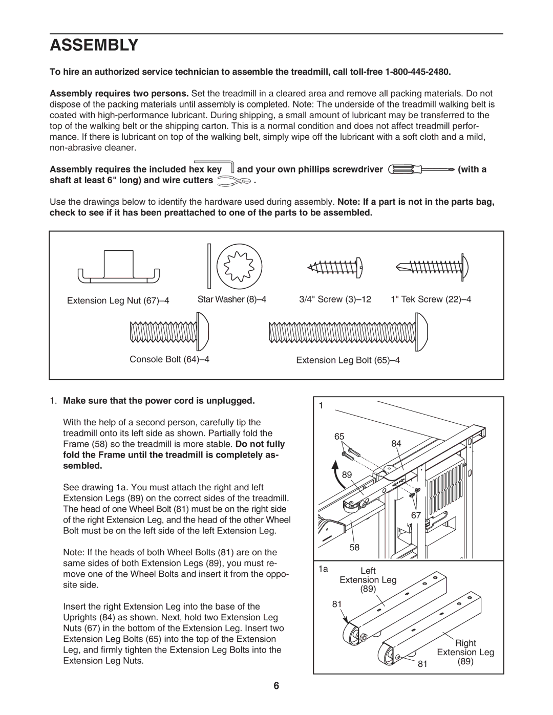
1. Make sure that the power cord is unplugged. | 1 |
|
|
|
|
| |
With the help of a second person, carefully tip the |
|
|
|
treadmill onto its left side as shown. Partially fold the |
| 65 |
|
Frame (58) so the treadmill is more stable. Do not fully |
|
| |
| 84 |
| |
fold the Frame until the treadmill is completely as- |
|
|
|
sembled. |
| 89 |
|
|
|
| |
See drawing 1a. You must attach the right and left |
|
|
|
Extension Legs (89) on the correct sides of the treadmill. |
|
|
|
The head of one Wheel Bolt (81) must be on the right side |
| 67 |
|
of the right Extension Leg, and the head of the other Wheel |
|
| |
|
|
| |
Bolt must be on the left side of the left Extension Leg. |
|
|
|
Note: If the heads of both Wheel Bolts (81) are on the |
| 58 |
|
|
|
| |
same sides of both Extension Legs (89), you must re- | 1a | Left |
|
move one of the Wheel Bolts and insert it from the oppo- |
| ||
| Extension Leg |
| |
site side. |
|
| |
| (89) |
| |
|
|
| |
Insert the right Extension Leg into the base of the |
| 81 |
|
Uprights (84) as shown. Next, hold two Extension Leg |
|
|
|
Nuts (67) in the bottom of the Extension Leg. Insert two |
|
|
|
Extension Leg Bolts (65) into the top of the Extension |
|
| Right |
Leg, and firmly tighten the Extension Leg Bolts into the |
|
| |
|
| Extension Leg | |
Extension Leg Nuts. |
| 81 | (89) |
|
|
|
6