ASSEMBLY
Assembly requires two persons. Set the treadmill in a cleared area and remove all packing materials. Do not dispose of the packing materials until assembly is completed. Note: The underside of the treadmill walking belt is coated with
Assembly requires the included hex keys | and your own phillips screwdriver | , rubber | |
mallet | , and adjustable wrench | . |
|
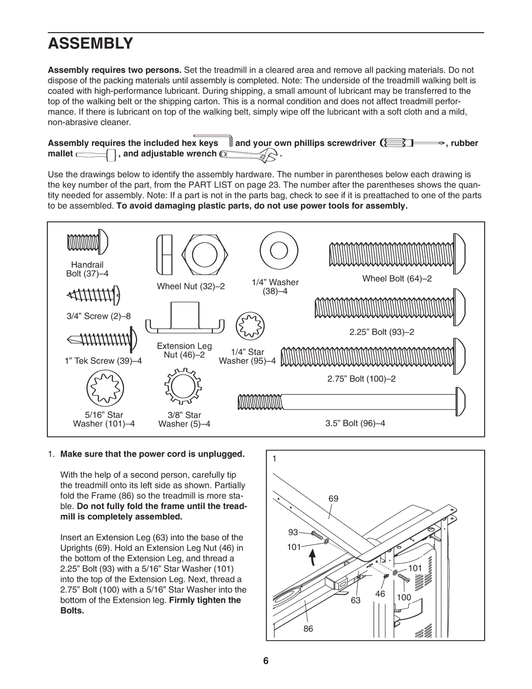
Use the drawings below to identify the assembly hardware. The number in parentheses below each drawing is the key number of the part, from the PART LIST on page 23. The number after the parentheses shows the quan- tity needed for assembly. Note: If a part is not in the parts bag, check to see if it is preattached to one of the parts to be assembled. To avoid damaging plastic parts, do not use power tools for assembly.
Handrail |
|
|
|
|
Bolt |
|
| 1/4” Washer | Wheel Bolt |
| Wheel Nut | |||
|
| |||
|
| |||
|
|
|
| |
3/4” Screw |
|
|
|
|
|
|
|
| 2.25” Bolt |
| Extension Leg |
| 1/4” Star |
|
| Nut |
|
| |
1” Tek Screw | Washer |
| ||
|
| |||
|
|
|
| 2.75” Bolt |
5/16” Star | 3/8” Star |
|
| 3.5” Bolt |
Washer | Washer |
|
| |
1. Make sure that the power cord is unplugged. | 1 |
|
| |
|
|
| ||
With the help of a second person, carefully tip |
|
|
| |
the treadmill onto its left side as shown. Partially |
|
|
| |
fold the Frame (86) so the treadmill is more sta- | 69 |
|
| |
ble. Do not fully fold the frame until the tread- |
|
| ||
|
|
| ||
mill is completely assembled. |
|
|
| |
Insert an Extension Leg (63) into the base of the | 93 |
|
| |
101 |
|
| ||
Uprights (69). Hold an Extension Leg Nut (46) in |
|
| ||
the bottom of the Extension Leg, and thread a |
|
| 101 | |
2.25” Bolt (93) with a 5/16” Star Washer (101) |
|
| ||
into the top of the Extension Leg. Next, thread a |
|
|
| |
2.75” Bolt (100) with a 5/16” Star Washer into the |
| 46 | 100 | |
bottom of the Extension leg. Firmly tighten the | 63 | |||
| ||||
|
| |||
Bolts. |
|
|
| |
| 86 |
|
| |
| 6 |
|
|