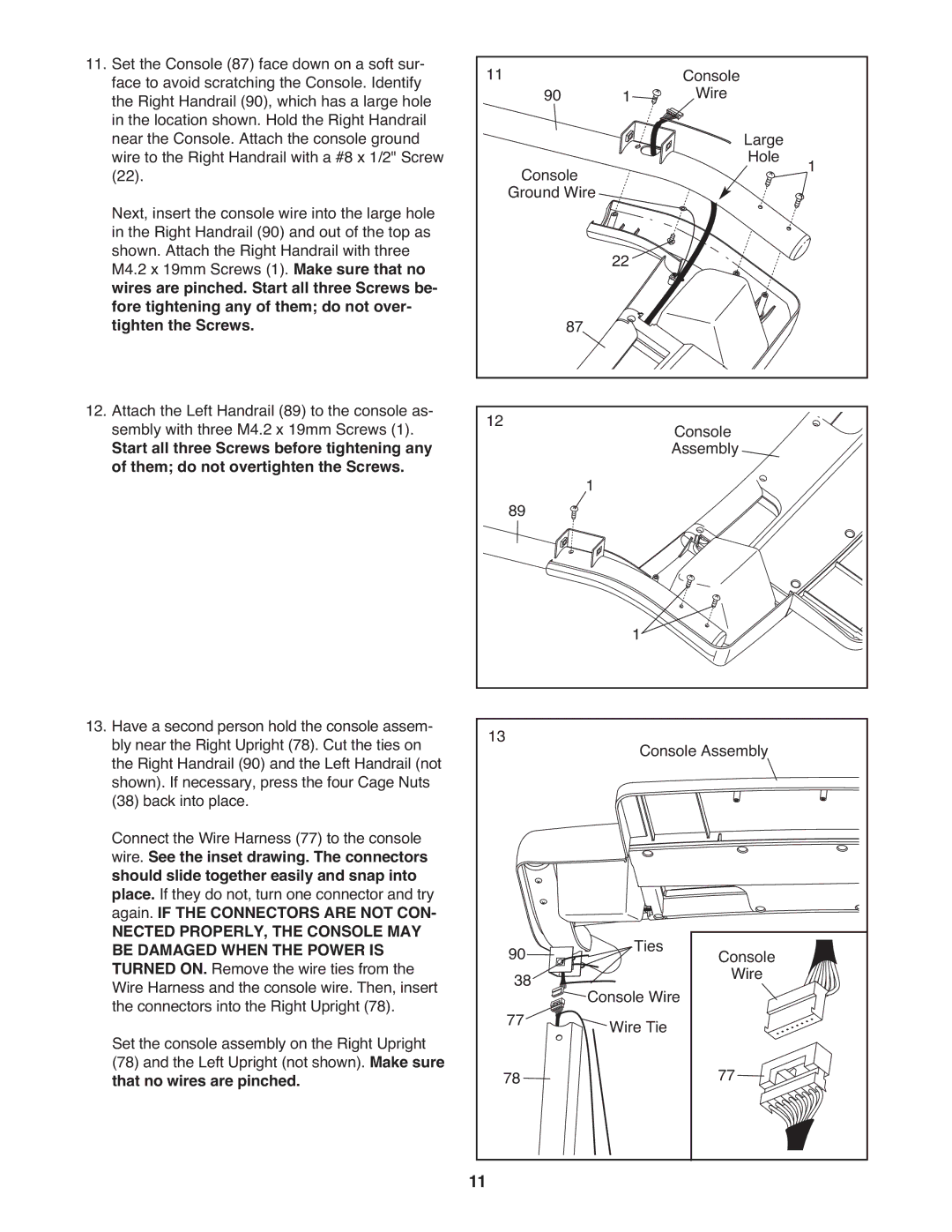
11. Set the Console (87) face down on a soft sur- | 11 |
|
|
| Console |
|
face to avoid scratching the Console. Identify | 90 |
| 1 |
| ||
the Right Handrail (90), which has a large hole |
|
| Wire |
| ||
in the location shown. Hold the Right Handrail |
|
|
|
| Large |
|
near the Console. Attach the console ground |
|
|
|
|
| |
wire to the Right Handrail with a #8 x 1/2" Screw |
| Console |
|
| Hole | 1 |
(22). |
|
|
|
| ||
Next, insert the console wire into the large hole |
| Ground Wire |
|
|
| |
in the Right Handrail (90) and out of the top as |
|
|
|
|
|
|
shown. Attach the Right Handrail with three |
|
|
| 22 |
|
|
M4.2 x 19mm Screws (1). Make sure that no |
|
|
|
|
| |
wires are pinched. Start all three Screws be- |
|
|
|
|
|
|
fore tightening any of them; do not over- |
| 87 |
|
|
|
|
tighten the Screws. |
|
|
|
|
| |
12. Attach the Left Handrail (89) to the console as- | 12 |
|
|
| Console |
|
sembly with three M4.2 x 19mm Screws (1). |
|
|
|
| ||
Start all three Screws before tightening any |
|
|
|
| Assembly |
|
of them; do not overtighten the Screws. |
| 89 | 1 |
|
|
|
|
|
|
|
| ||
|
|
|
|
|
| |
|
|
|
|
| 1 |
|
13. Have a second person hold the console assem- | 13 |
|
|
|
|
|
bly near the Right Upright (78). Cut the ties on |
|
|
| Console Assembly |
| |
the Right Handrail (90) and the Left Handrail (not |
|
|
|
|
| |
shown). If necessary, press the four Cage Nuts |
|
|
|
|
|
|
(38) back into place. |
|
|
|
|
|
|
Connect the Wire Harness (77) to the console |
|
|
|
wire. See the inset drawing. The connectors |
|
|
|
should slide together easily and snap into |
|
|
|
place. If they do not, turn one connector and try |
|
|
|
again. IF THE CONNECTORS ARE NOT CON- |
|
|
|
NECTED PROPERLY, THE CONSOLE MAY |
| Ties |
|
BE DAMAGED WHEN THE POWER IS | 90 | Console | |
TURNED ON. Remove the wire ties from the |
| ||
Wire Harness and the console wire. Then, insert | 38 | Console Wire | Wire |
the connectors into the Right Upright (78). | 77 |
| |
Set the console assembly on the Right Upright | Wire Tie |
| |
(78) and the Left Upright (not shown). Make sure | 78 |
| 77 |
that no wires are pinched. |
|
11