Verifying Scanner Operation
Once a charged battery has been installed in the scanner, scan the sample bar codes in the back of this manual that correspond to the symbologies your scanner is programmed to read. If unsure how to do this, see the section on How to Scan in this manual. The system may signal with one or a combination of indicators depending upon how the scanner and Base Station are programmed to respond (see LED and Beeper Indications for details). If your scanner fails to read a sample bar code of a symbology it’s programmed to read, turn to the section titled, Troubleshooting.
Connecting the Base Station to the Host Terminal
| It is important that the interface (I/F) cable be con- | |
| nected to the Base Station prior to applying power | |
| to the system. This is because the interface type | |
| ||
NOTE | the Base Station subject to the I/F cable it is con- | |
nected to at the time of | ||
|
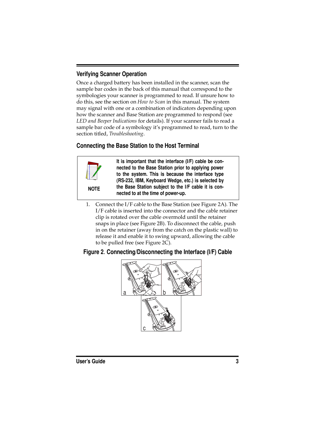
1.Connect the I/F cable to the Base Station (see Figure 2A). The I/F cable is inserted into the connector and the cable retainer clip is rotated over the cable overmold until the retainer snaps in place (see Figure 2B). To disconnect the cable, push in on the retainer (away from the catch on the plastic wall) to release it and enable it to swing upward, allowing the cable to be pulled free (see Figure 2C).
Figure 2. Connecting/Disconnecting the Interface (I/F) Cable
a ![]() b
b
c
User’s Guide | 3 |