PVI Industries 180, 150 manual Remote Connections Terminal Strip

Models: 150 180

1 44
Download 44 pages 43.39 Kb
Page 26
Image 26

12

REMOTE CONNECTIONS – TERMINAL STRIP


12.1

Making BMS/BAS remote connections for analog and binary (on/off) signals


A terminal strip for the remote connection is located behind the hinged control panel at the top of the cabinet and is


accessed by removing the bottom cover and then removing the screws at the top of the hinged cover.


Important: Do not use single strand bell wire for remote field connections to terminals R1-R2 and C1-C2. Use only


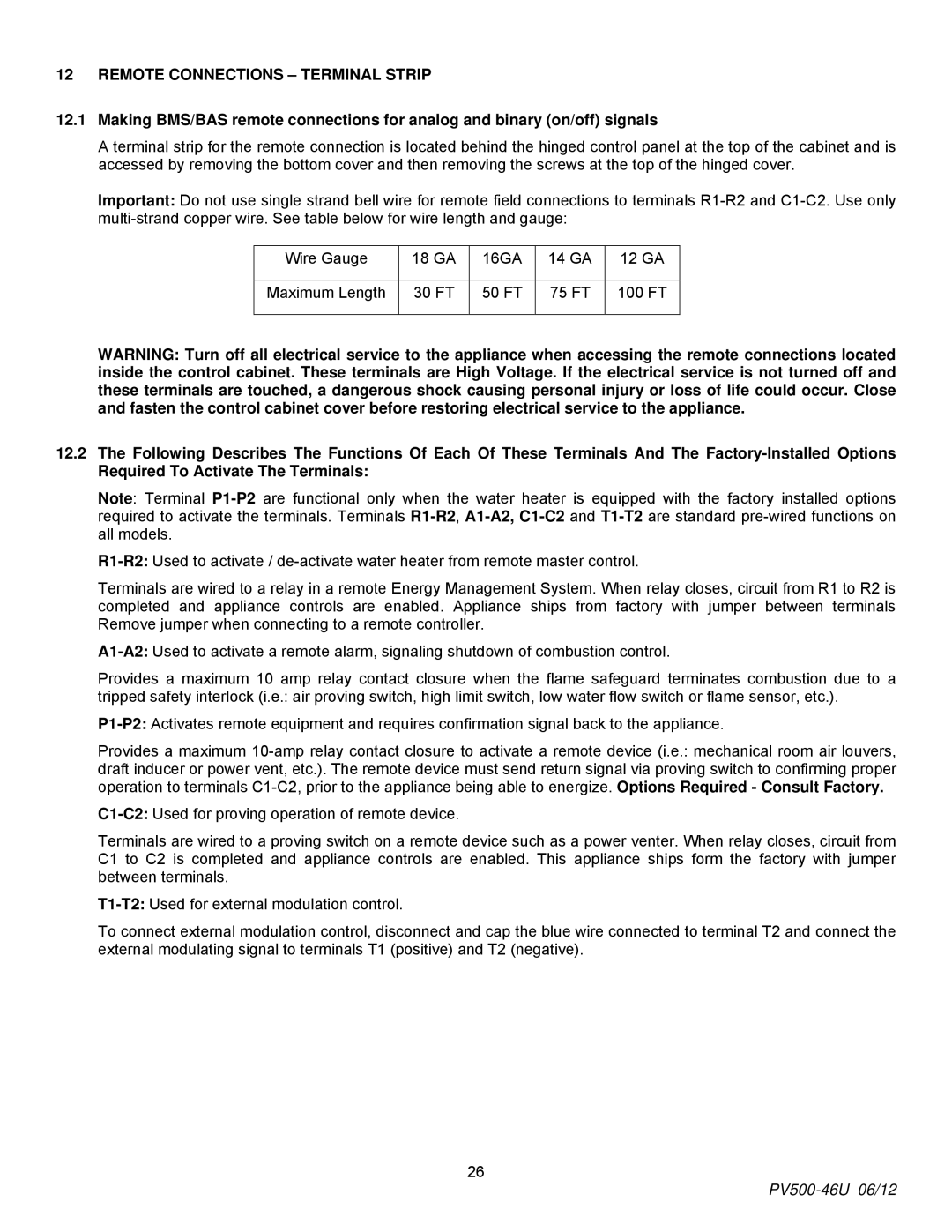
multi-strand copper wire. See table below for wire length and gauge:


Wire Gauge

18 GA

16GA

14 GA

12 GA


Maximum Length

30 FT

50 FT

75 FT

100 FT


WARNING: Turn off all electrical service to the appliance when accessing the remote connections located


inside the control cabinet. These terminals are High Voltage. If the electrical service is not turned off and


these terminals are touched, a dangerous shock causing personal injury or loss of life could occur. Close


and fasten the control cabinet cover before restoring electrical service to the appliance.

12.2

The Following Describes The Functions Of Each Of These Terminals And The Factory-Installed Options


Required To Activate The Terminals:


Note: Terminal P1-P2are functional only when the water heater is equipped with the factory installed options required to activate the terminals. Terminals R1-R2, A1-A2,C1-C2and T1-T2are standard pre-wired functions on all models.

R1-R2:Used to activate / de-activate water heater from remote master control.

Terminals are wired to a relay in a remote Energy Management System. When relay closes, circuit from R1 to R2 is completed and appliance controls are enabled. Appliance ships from factory with jumper between terminals Remove jumper when connecting to a remote controller.

A1-A2:Used to activate a remote alarm, signaling shutdown of combustion control.

Provides a maximum 10 amp relay contact closure when the flame safeguard terminates combustion due to a tripped safety interlock (i.e.: air proving switch, high limit switch, low water flow switch or flame sensor, etc.).

P1-P2:Activates remote equipment and requires confirmation signal back to the appliance.

Provides a maximum 10-amp relay contact closure to activate a remote device (i.e.: mechanical room air louvers, draft inducer or power vent, etc.). The remote device must send return signal via proving switch to confirming proper operation to terminals C1-C2, prior to the appliance being able to energize. Options Required - Consult Factory.

C1-C2:Used for proving operation of remote device.

Terminals are wired to a proving switch on a remote device such as a power venter. When relay closes, circuit from C1 to C2 is completed and appliance controls are enabled. This appliance ships form the factory with jumper between terminals.

T1-T2:Used for external modulation control.

To connect external modulation control, disconnect and cap the blue wire connected to terminal T2 and connect the external modulating signal to terminals T1 (positive) and T2 (negative).

26

PV500-46U 06/12

Page 26
Image 26
PVI Industries 180, 150 manual Remote Connections Terminal Strip

150, 180 specifications

PVI Industries has established itself as a prominent manufacturer in the water heating industry, particularly known for its range of commercial water heaters. Among their well-regarded products is the PVI Industries 150,180, a robust unit engineered to meet the demanding needs of various commercial applications.

The PVI Industries 150,180 is designed to deliver high-efficiency performance, catering primarily to large-scale operations such as hotels, hospitals, and other facilities that require a constant supply of hot water. The unit boasts impressive heating capacity, enabling it to serve multiple points of use simultaneously. With a focus on reliability and durability, the construction of the 150,180 incorporates high-quality materials that ensure longevity even in the most challenging environments.

One of the standout features of the PVI 150,180 is its advanced heating technology. The unit utilizes a state-of-the-art gas-fired burner system, which not only ensures rapid heating but also maximizes energy efficiency. This attention to energy performance is crucial for businesses aiming to reduce operational costs and minimize their environmental impact. Furthermore, the unit supports a range of fuel types, including natural gas and propane, providing flexibility for different regional needs and preferences.

From a technological standpoint, the PVI Industries 150,180 includes an intuitive control system that allows users to monitor and adjust settings easily. This sophisticated interface provides real-time data on water temperature, operational status, and maintenance alerts, significantly enhancing user experience and system management.

Safety features are paramount in PVI’s design philosophy. The 150,180 comes equipped with multiple safety mechanisms, including a high-temperature limit switch and a pressure relief valve, ensuring safe operation and compliance with strict industry regulations.

In terms of installation, the PVI Industries 150,180 is engineered with versatility in mind. It can be installed in various configurations, making it adaptable to the spatial constraints of any facility. Maintenance is straightforward, with accessible components designed to reduce downtime and service costs.

Overall, the PVI Industries 150,180 represents a leading choice for commercial water heating solutions, characterized by its efficiency, reliability, and advanced technology, meeting the diverse needs of modern businesses while upholding the highest standards of safety and performance.