Connections
Making the required connections to the DCM is simple. Just make sure that you have all of the correct cables.
Required Cables
1-
2- QSC DataPort cable for every amplifier channel pair (8 to 19 cables depending upon model)
3- Cinema Processor cable (DB25
4- USB Type A to Type B device cable.
5- Shielded audio cables for Auxiliary Input, Hearing Impaired, and Powered Subwoofer outputs (if used)
AC Mains
Before plugging your DCM into the AC mains, verify proper operating voltage. The serial number sticker located on the rear of the DCM has the rated operating voltage information printed on it. Locate the sticker, note the rated voltage, and ensure the AC circuit you intend to use is properly rated.
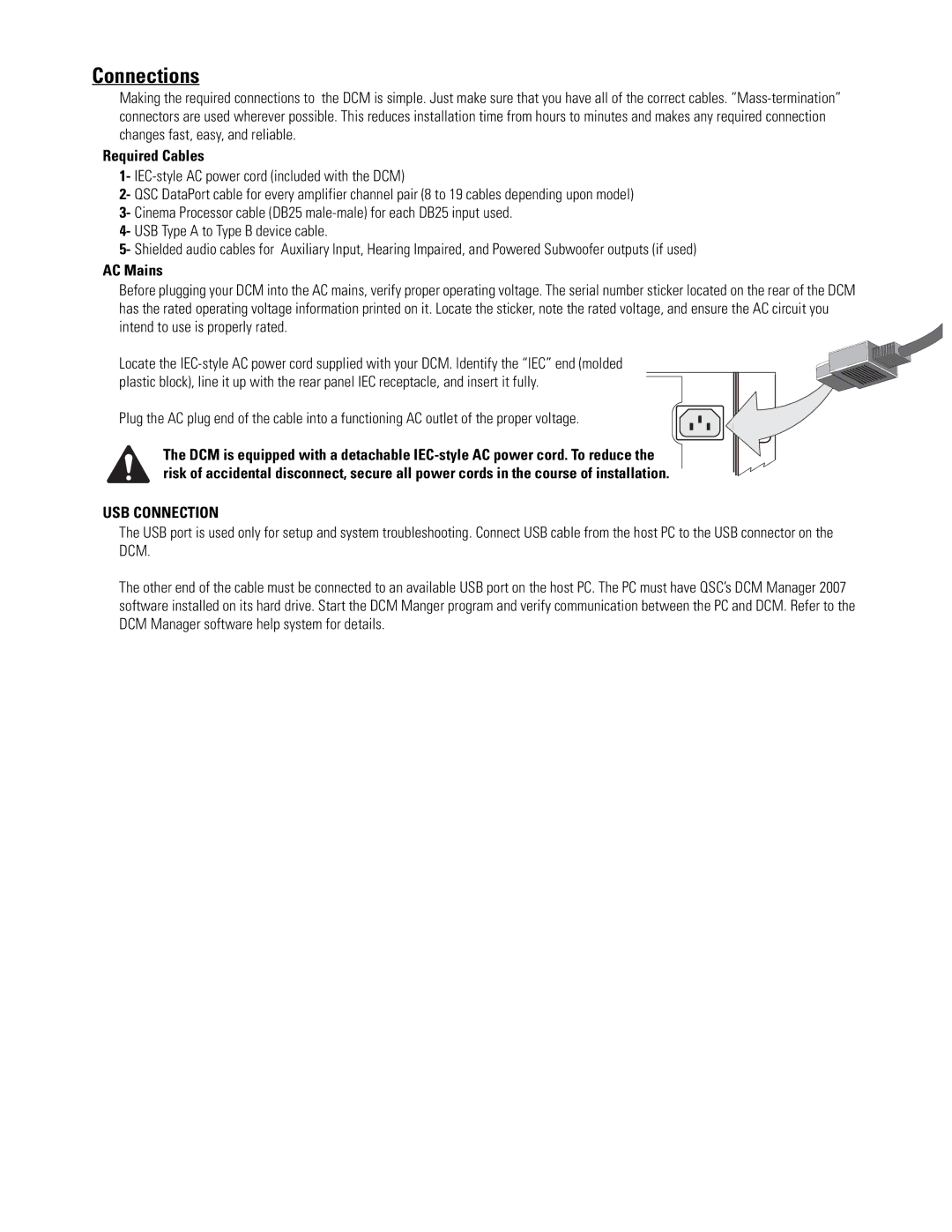
Locate the
Plug the AC plug end of the cable into a functioning AC outlet of the proper voltage.
The DCM is equipped with a detachable
USB CONNECTION
The USB port is used only for setup and system troubleshooting. Connect USB cable from the host PC to the USB connector on the DCM.
The other end of the cable must be connected to an available USB port on the host PC. The PC must have QSC’s DCM Manager 2007 software installed on its hard drive. Start the DCM Manger program and verify communication between the PC and DCM. Refer to the DCM Manager software help system for details.