Hardware Description
Front Panel
The front panel of the DCM series resembles traditional cinema monitor products. This provides the projectionist a well known and easy to understand interface.
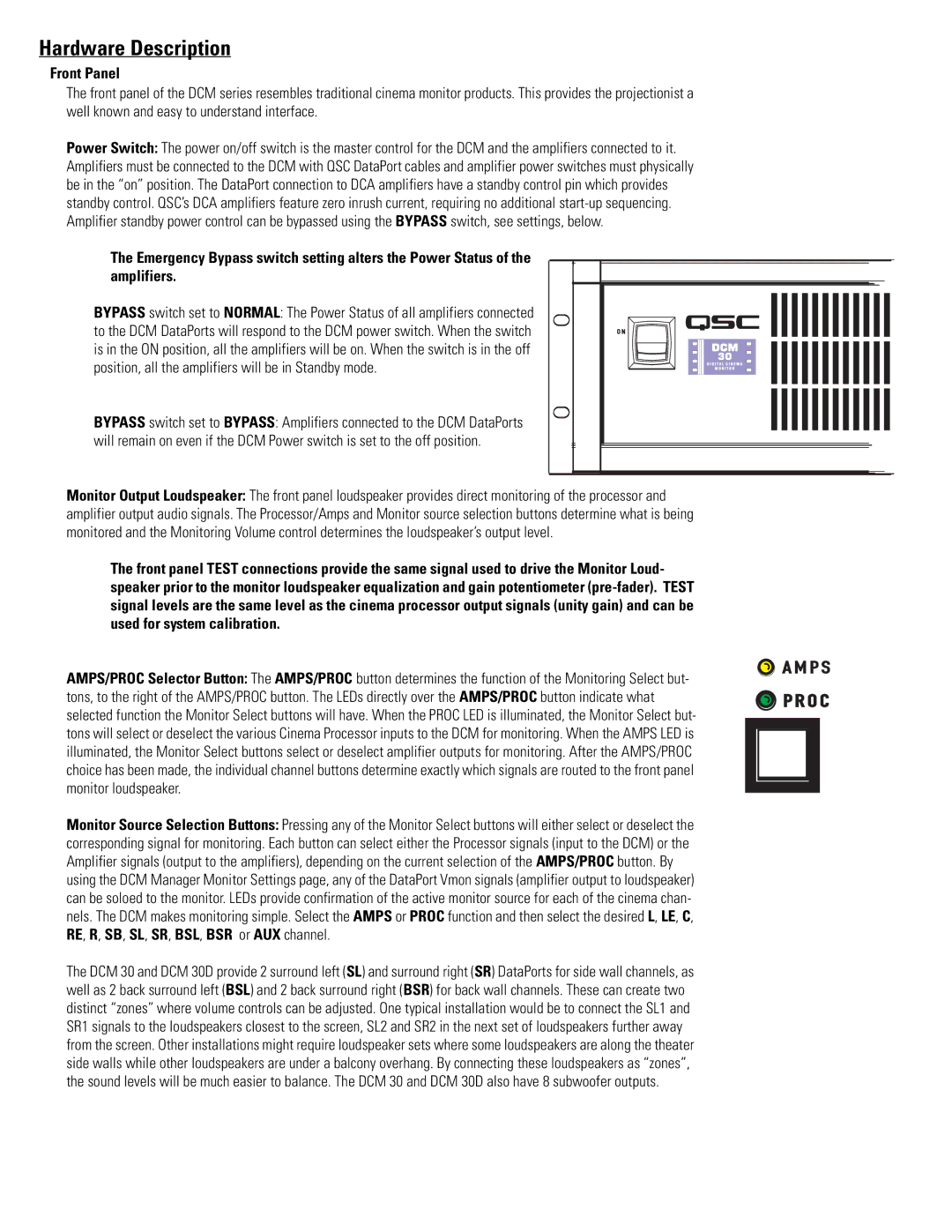
Power Switch: The power on/off switch is the master control for the DCM and the amplifiers connected to it. Amplifiers must be connected to the DCM with QSC DataPort cables and amplifier power switches must physically be in the “on” position. The DataPort connection to DCA amplifiers have a standby control pin which provides standby control. QSC’s DCA amplifiers feature zero inrush current, requiring no additional
The Emergency Bypass switch setting alters the Power Status of the amplifiers.
BYPASS switch set to NORMAL: The Power Status of all amplifiers connected to the DCM DataPorts will respond to the DCM power switch. When the switch is in the ON position, all the amplifiers will be on. When the switch is in the off position, all the amplifiers will be in Standby mode.
BYPASS switch set to BYPASS: Amplifiers connected to the DCM DataPorts will remain on even if the DCM Power switch is set to the off position.
Monitor Output Loudspeaker: The front panel loudspeaker provides direct monitoring of the processor and amplifier output audio signals. The Processor/Amps and Monitor source selection buttons determine what is being monitored and the Monitoring Volume control determines the loudspeaker’s output level.
The front panel TEST connections provide the same signal used to drive the Monitor Loud- speaker prior to the monitor loudspeaker equalization and gain potentiometer
AMPS/PROC Selector Button: The AMPS/PROC button determines the function of the Monitoring Select but- tons, to the right of the AMPS/PROC button. The LEDs directly over the AMPS/PROC button indicate what selected function the Monitor Select buttons will have. When the PROC LED is illuminated, the Monitor Select but- tons will select or deselect the various Cinema Processor inputs to the DCM for monitoring. When the AMPS LED is illuminated, the Monitor Select buttons select or deselect amplifier outputs for monitoring. After the AMPS/PROC choice has been made, the individual channel buttons determine exactly which signals are routed to the front panel monitor loudspeaker.
Monitor Source Selection Buttons: Pressing any of the Monitor Select buttons will either select or deselect the corresponding signal for monitoring. Each button can select either the Processor signals (input to the DCM) or the Amplifier signals (output to the amplifiers), depending on the current selection of the AMPS/PROC button. By using the DCM Manager Monitor Settings page, any of the DataPort Vmon signals (amplifier output to loudspeaker) can be soloed to the monitor. LEDs provide confirmation of the active monitor source for each of the cinema chan- nels. The DCM makes monitoring simple. Select the AMPS or PROC function and then select the desired L, LE, C, RE, R, SB, SL, SR, BSL, BSR or AUX channel.
The DCM 30 and DCM 30D provide 2 surround left (SL) and surround right (SR) DataPorts for side wall channels, as well as 2 back surround left (BSL) and 2 back surround right (BSR) for back wall channels. These can create two distinct “zones” where volume controls can be adjusted. One typical installation would be to connect the SL1 and SR1 signals to the loudspeakers closest to the screen, SL2 and SR2 in the next set of loudspeakers further away from the screen. Other installations might require loudspeaker sets where some loudspeakers are along the theater side walls while other loudspeakers are under a balcony overhang. By connecting these loudspeakers as “zones”, the sound levels will be much easier to balance. The DCM 30 and DCM 30D also have 8 subwoofer outputs.