2 Hardware Configuration
The
This chapter lists a number of optional jumper settings that control various hardware features. Jumpers J2,
2.1 Factory Default Configuration
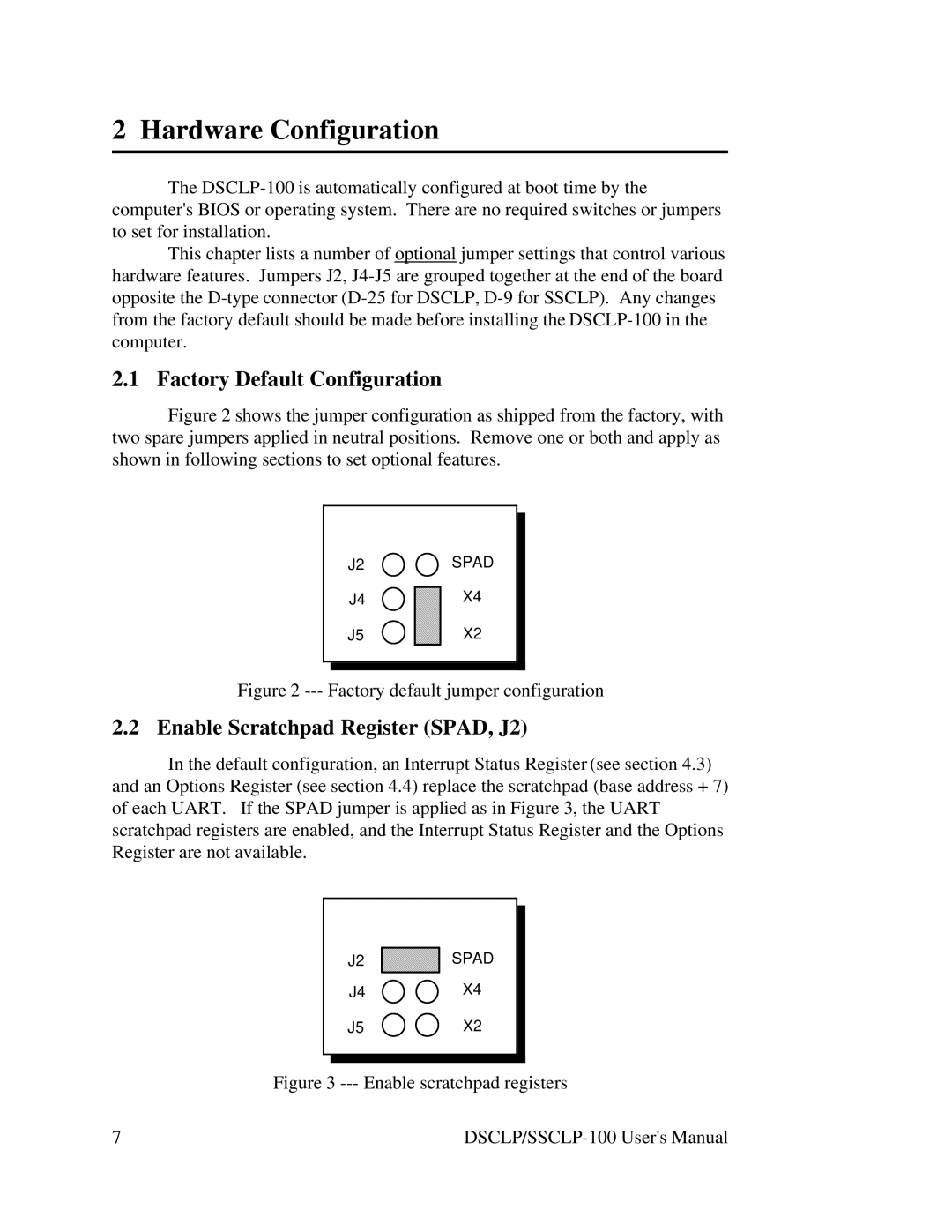
Figure 2 shows the jumper configuration as shipped from the factory, with two spare jumpers applied in neutral positions. Remove one or both and apply as shown in following sections to set optional features.
J2
J4
J5
SPAD
X4
X2
Figure 2 --- Factory default jumper configuration
2.2 Enable Scratchpad Register (SPAD, J2)
In the default configuration, an Interrupt Status Register (see section 4.3) and an Options Register (see section 4.4) replace the scratchpad (base address + 7) of each UART. If the SPAD jumper is applied as in Figure 3, the UART scratchpad registers are enabled, and the Interrupt Status Register and the Options Register are not available.
J2
J4
J5
SPAD
X4
X2
Figure 3 --- Enable scratchpad registers
7 |