8 CONFIGURATION REGISTER
The
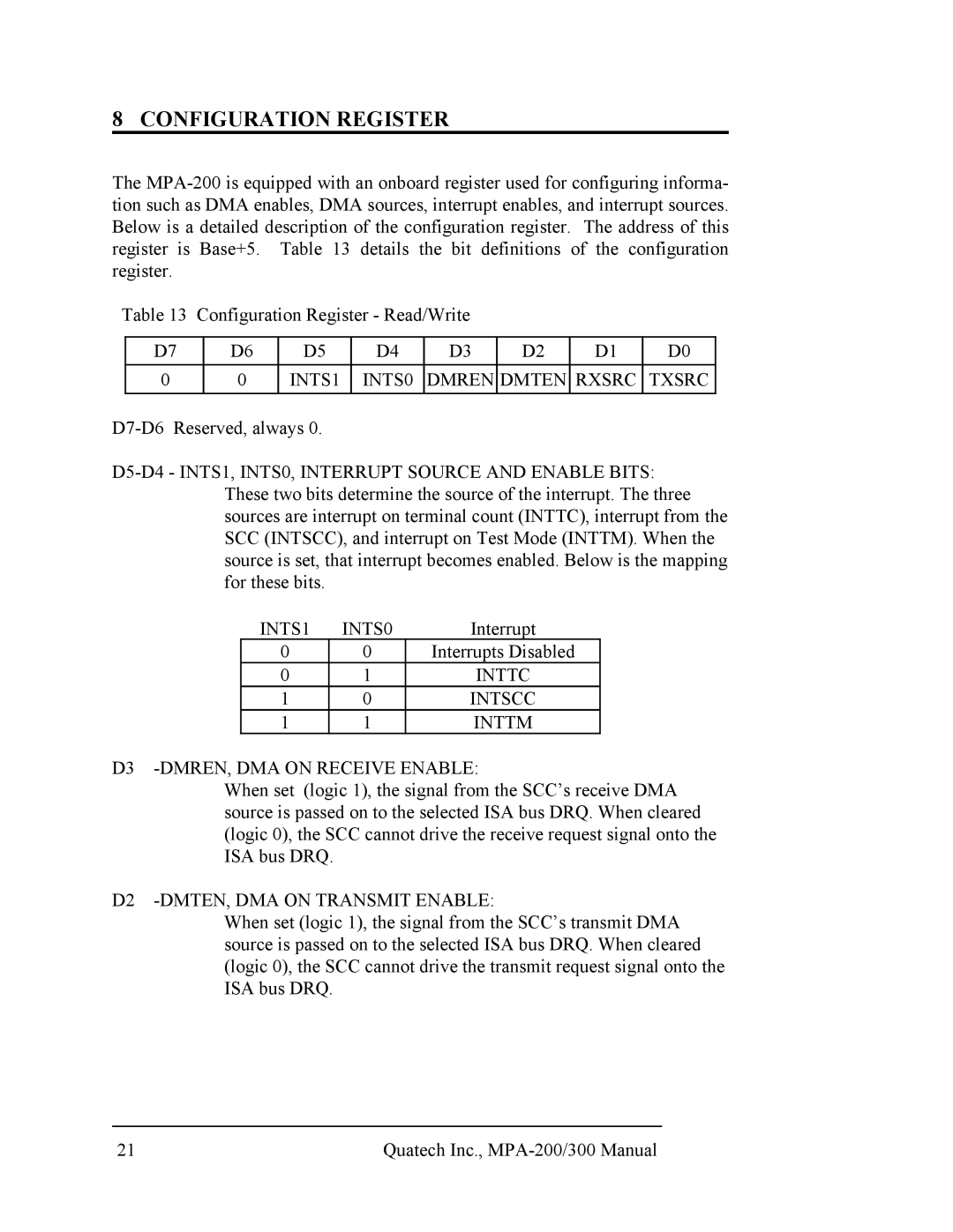
Table 13 | Configuration Register - Read/Write |
|
|
| |||||
|
|
|
|
|
|
|
|
|
|
| D7 |
| D6 | D5 | D4 | D3 | D2 | D1 | D0 |
| 0 |
| 0 | INTS1 | INTS0 | DMREN | DMTEN | RXSRC | TXSRC |
INTS1 | INTS0 | Interrupt |
0 | 0 | Interrupts Disabled |
0 | 1 | INTTC |
1 | 0 | INTSCC |
1 | 1 | INTTM |
D3 -DMREN, DMA ON RECEIVE ENABLE:
When set (logic 1), the signal from the SCC’s receive DMA source is passed on to the selected ISA bus DRQ. When cleared (logic 0), the SCC cannot drive the receive request signal onto the ISA bus DRQ.
D2 -DMTEN, DMA ON TRANSMIT ENABLE:
When set (logic 1), the signal from the SCC’s transmit DMA source is passed on to the selected ISA bus DRQ. When cleared (logic 0), the SCC cannot drive the transmit request signal onto the ISA bus DRQ.
21 | Quatech Inc., |
