T1, E1 specifications
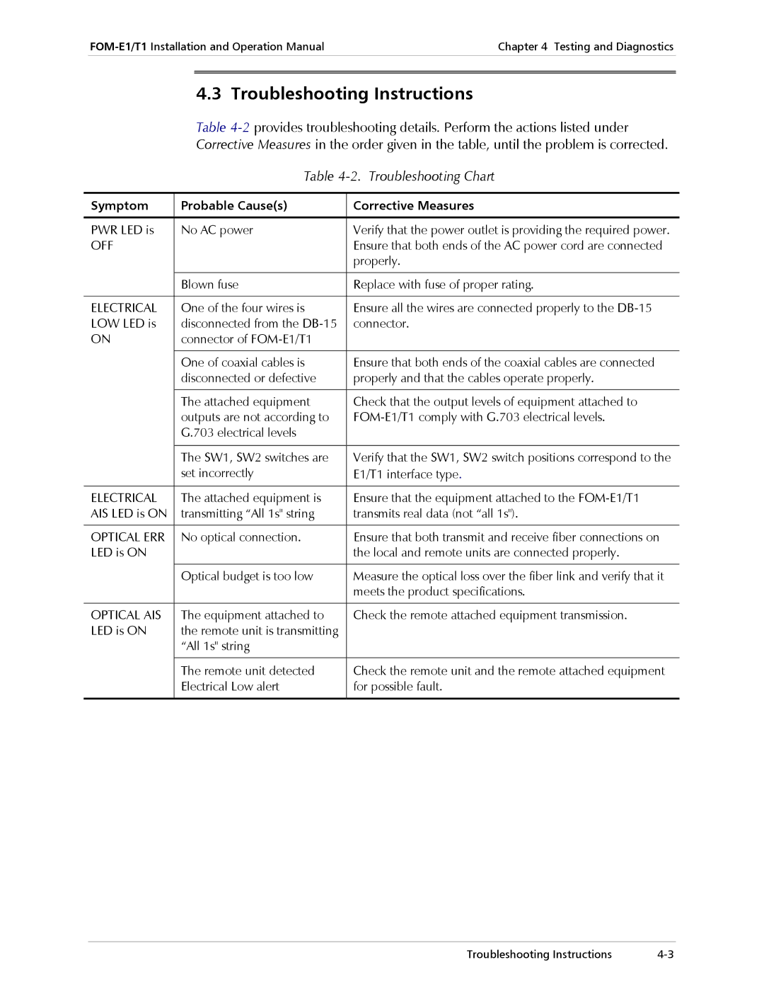
RAD Data Communication specializes in providing advanced networking solutions, particularly for E1 and T1 lines. These digital transmission systems are pivotal in telecommunications, allowing for efficient data transfer, voice communication, and multimedia services.E1 and T1 lines are standardized digital circuits offering capacity for multiple channels. A T1 line, commonly used in North America, accommodates data transmission at a rate of 1.544 Mbps, while an E1 line, predominantly used in Europe and other parts of the world, supports a rate of 2.048 Mbps. Each line can carry multiple voice channels—up to 24 for T1 and 32 for E1—making them suitable for both voice and data services.
One of the main features of RAD's E1 and T1 solutions is their versatility. These lines can be utilized in various applications, including traditional telephony, private branch exchanges (PBXs), and modern Voice over IP (VoIP) networks. RAD's solutions enable users to seamlessly migrate from older systems to more integrated and efficient digital networks without sacrificing performance.
RAD Data Communication focuses on ensuring reliability and robustness in their E1 and T1 offerings. With built-in error detection mechanisms, such as cyclic redundancy check (CRC), these systems maintain high levels of data integrity. In addition, RAD’s devices often incorporate advanced features like Adaptive Rate Control, allowing for dynamic adjustments to accommodate varying network conditions.
Technology-wise, RAD integrates advanced protocols and features, such as Frame Relay and Multiprotocol Label Switching (MPLS), into their E1 and T1 equipment. This flexibility supports the transmission of diverse data types, ensuring users can transition smoothly between legacy systems and modern technologies.
Another characteristic that sets RAD's products apart is their management capabilities. Many devices come equipped with SNMP (Simple Network Management Protocol) support, enabling remote monitoring and management. This feature is essential for network administrators seeking to maintain optimal performance and quickly address potential issues.
Moreover, RAD's E1 and T1 solutions are designed for easy integration into existing network infrastructures. Their compact and modular design allows for straightforward installation and scalability, accommodating future growth and technology advancements without major overhauls.
In summary, RAD Data Communication’s E1 and T1 solutions are characterized by their reliability, versatility, and advanced management features. Designed to meet the evolving needs of communication networks, they ensure that users can take full advantage of both traditional and modern telecommunications technologies.

