❒ 5b.
❒ 6. Install C3, the other compression trimmer, just like C1.
❒ 7a. Bend the leads of C2, the round trimmer capacitor, at right angles so that it can also sit in a level and flat position. The two leads at one end go to the ground plane, and the single lead goes to the pad with C1.
❒ 7b. Install C2.
❒ 8. Install C4, just like C2. Now that you are accustomed to how easy good
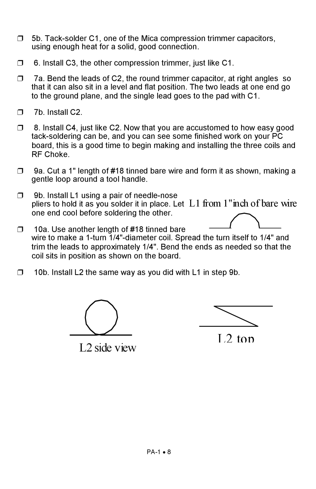
❒ 9a. Cut a 1" length of #18 tinned bare wire and form it as shown, making a gentle loop around a tool handle.
❒ 9b. Install L1 using a pair of
pliers to hold it as you solder it in place. Let L1 from 1"inch of bare wire one end cool before soldering the other.
❒10a. Use another length of #18 tinned bare
wire to make a
❒10b. Install L2 the same way as you did with L1 in step 9b.
L2 side view