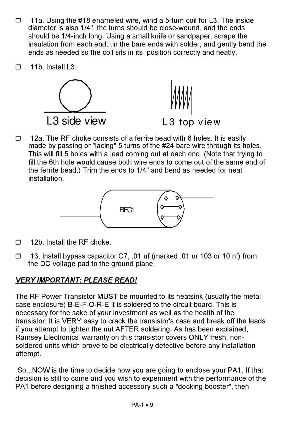
❒11a. Using the #18 enameled wire, wind a
❒11b. Install L3.
L3 side view | L 3 to p v ie w |
❒12a. The RF choke consists of a ferrite bead with 6 holes. It is easily made by passing or "lacing" 5 turns of the #24 bare wire through its holes. This will fill 5 holes with a lead coming out at each end. (Note that trying to fill the 6th hole would cause both wire ends to come out of the same end of the ferrite bead.) Trim the ends to 1/4" and bend as needed for neat installation.
RFC1
❒12b. Install the RF choke.
❒13. Install bypass capacitor C7, .01 uf (marked .01 or 103 or 10 nf) from the DC voltage pad to the ground plane.
VERY IMPORTANT: PLEASE READ!
The RF Power Transistor MUST be mounted to its heatsink (usually the metal case enclosure)
So...NOW is the time to decide how you are going to enclose your PA1. If that decision is still to come and you wish to experiment with the performance of the PA1 before designing a finished accessory such a "docking booster", then
