Servicing Notes

Disconnect from electricity supply before commencing servicing, particularly before removing any of the following: control panel, side panels, ceramic hob, or any of the electrical components or cover boxes. Before electrical reconnection check that the appliance is electrically safe.

1.To Remove a Side Panel

Disconnect from electricity supply. Pull the cooker forward.

Pull off the push fi t control panel end caps at each end and remove the end fi xing screws under the end cap.

Remove the retaining screws for each panel (1 at the front and 2 at the rear). The lower front retaining screws (one each side) are situated beneath the lower edge at the front corners of the side panels

Reassemble in reverse order.

2.To Lift up the Ceramic Hob

Pull the cooker forward.

Pull off the push fi t control panel end caps at each end and remove the end fi xing screws under the end cap.

Remove the lower front retaining screws (one each side) situated beneath the lower edge at the front corners of the side panels.

Swing the side panels to gain access to the hob

xing screws (1 each side) at the top front of the side uprights. Remove these screws.

Caution

The ceramic hob material is much more sensitive to scratches on the underside than the top.

Lift up the ceramic hob at the front and prop in position with a non-metallic prop.

Take care not to touch or scratch the underside of the ceramic as this will weaken the material and cause the top to shatter.

3. To replace a hob element.

Lift up the ceramic hob see 2. The elements are now accessible.

4To Remove the Control Panel

Disconnect from electricity supply.

Remove the handrail by removing the 2 end bracket fi xing screws.

Pull off the push fi t control panel end caps at each end and remove the end fi xing screws under the end cap.

Pull off all the control knobs. Open the grill and oven doors and remove the control panel fi xing screws underneath the control panel. The screws directly below the clock are for the clock fi xing bracket - don’t remove them at this stage.

Lift the control panel, pull forward and disconnect the wiring from the rear.

Reassemble in reverse order. When replacing leads refer to the wiring diagram. Check operation of timer.

5.To Remove Oven Light Switch

Remove control panel (see 4).

NB The old switch may be destroyed during removal.

Remove switch button and old switch from its bezel by gripping the switch body behind the control panel and twisting sharply.

The switch bezel can then be removed by folding back its locking wings and pushing forward. Fit the new bezel to the control panel by fi rst lining up the raised key on its body with the cut-out in the control panel and pushing it in from the front. Assemble the new switch to the bezel by lining up the key sections and pushing home. Fit the new button by pushing in from the front.

Replace control panel in reverse order and test for correct operation.

6.To Remove Electronic Timer

Disconnect from electricity supply.

Pull off the timer control buttons and remove the control panel (See 4). Remove the timer/mounting bracket assembly from the control panel by removing the two fi xing screws. Remove the timer from its mounting bracket by depressing the plastic lugs

on the timer case, at the same time pulling the unit forward.

Reassemble in reverse order. When replacing leads refer to the wiring diagram. Check operation of timer.

33

Page 33
Image 33
Rangemaster U105510-01 manual Servicing Notes

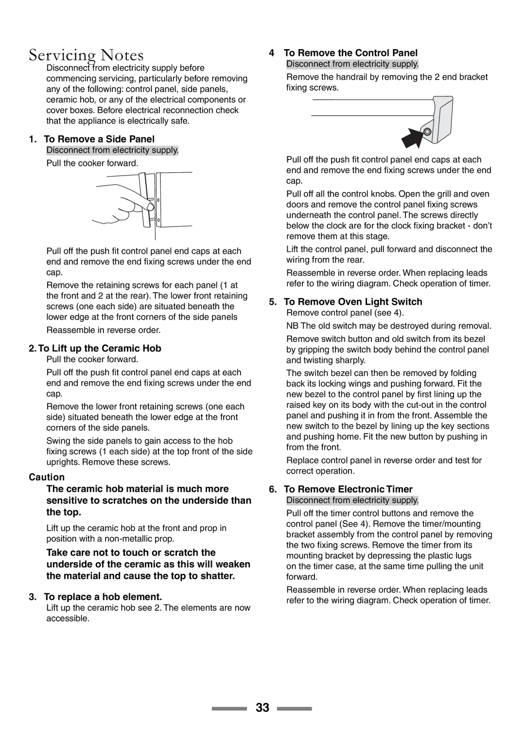
U105510-01 specifications

The Rangemaster U105510-01 is an exceptional kitchen appliance that perfectly blends functionality and style, making it a must-have for discerning chefs and home cooks alike. This model is a showcase of advanced technology, robust construction, and user-friendly features, ensuring an efficient cooking experience.

One of the standout characteristics of the U105510-01 is its dual fuel capability. Integrating both gas and electric cooking methods, this range allows culinary enthusiasts to harness the precision of gas for high-heat searing alongside the even baking and roasting performance afforded by an electric oven. This versatility makes it an ideal choice for various cooking techniques.

The U105510-01 comes equipped with multiple cooking zones on its cooktop, featuring powerful burners that deliver rapid heat. With varying BTU ratings, users can easily switch between simmering delicate sauces and boiling water for pasta. The cast iron grates not only add durability but also provide a professional aesthetic, contributing to the range's impressive overall appeal.

In terms of oven features, the Rangemaster U105510-01 boasts a spacious interior with multiple shelves and versatile cooking modes. The oven includes a fan-assisted convection system that ensures even heat distribution, perfect for baking and roasting. The built-in thermometer allows chefs to monitor their cooking precisely, resulting in perfectly cooked dishes every time.

Safety is paramount in the design of the Rangemaster U105510-01. The unit features a flame failure device that automatically cuts off the gas supply should the flame go out. Additionally, the range is designed for easy cleaning, with removable oven doors and smooth surfaces that can be wiped down easily, ensuring that maintenance is hassle-free.

Aesthetically, the U105510-01 is available in various colors and finishes, enabling it to complement virtually any kitchen décor. Its sleek lines and commercial-style knobs deliver an attractive presence in modern and traditional kitchens alike.

In summary, the Rangemaster U105510-01 is a remarkable blend of innovative technology, robust performance, and sophisticated design. With its dual fuel capabilities, powerful burners, spacious oven, safety features, and stylish appearance, it is undoubtedly an excellent addition to any culinary space, catering to the needs of both amateur and professional cooks.