WARNING – SERVICING TO BE CARRIED OUT ONLY BY AN AUTHORISED PERSON
Disconnect from electricity before servicing. Check appliance is safe when you have finished.
8. Servicing
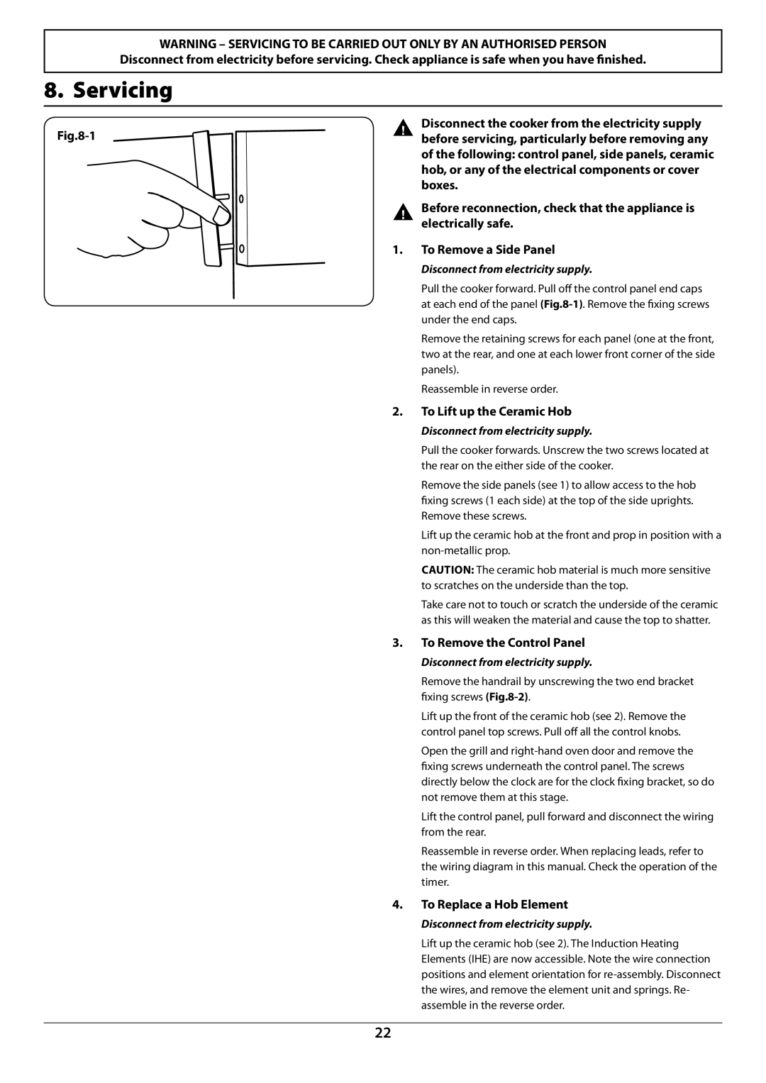
ArtNo.210-0008 - Classic Removing the end caps
Disconnect the cooker from the electricity supply before servicing, particularly before removing any of the following: control panel, side panels, ceramic hob, or any of the electrical components or cover boxes.
Before reconnection, check that the appliance is electrically safe.
1.To Remove a Side Panel
Disconnect from electricity supply.
Pull the cooker forward. Pull off the control panel end caps at each end of the panel
Remove the retaining screws for each panel (one at the front, two at the rear, and one at each lower front corner of the side panels).
Reassemble in reverse order.
2.To Lift up the Ceramic Hob
Disconnect from electricity supply.
Pull the cooker forwards. Unscrew the two screws located at the rear on the either side of the cooker.
Remove the side panels (see 1) to allow access to the hob fixing screws (1 each side) at the top of the side uprights. Remove these screws.
Lift up the ceramic hob at the front and prop in position with a
CAUTION: The ceramic hob material is much more sensitive to scratches on the underside than the top.
Take care not to touch or scratch the underside of the ceramic as this will weaken the material and cause the top to shatter.
3.To Remove the Control Panel
Disconnect from electricity supply.
Remove the handrail by unscrewing the two end bracket fixing screws
Lift up the front of the ceramic hob (see 2). Remove the control panel top screws. Pull off all the control knobs.
Open the grill and
Lift the control panel, pull forward and disconnect the wiring from the rear.
Reassemble in reverse order. When replacing leads, refer to the wiring diagram in this manual. Check the operation of the timer.
4.To Replace a Hob Element
Disconnect from electricity supply.
Lift up the ceramic hob (see 2). The Induction Heating Elements (IHE) are now accessible. Note the wire connection positions and element orientation for
22