Type 150/400 Autopilot System
Type 150/400 Autopilot System Installation Guide
Contents
Maintenance
Specifications
Glossary Index
About this handbook
Warranty
Safety notices
Important Information
EMC conformance
Handbook information
Viii
Check the Installation Kit
Autopilot system core pack contents
Read this handbook
Type 150G
Compass
Rudder position sensor
Type 400G
Drive unit
Autopilot system other key components
Autopilot system extended systems
Control unit
Obtain installation tools
Check parts supplied
Core pack parts supplied
Course computer components
D5378-1
Identify suitable locations
EMC installation guidelines
Rotary rudder position sensor location
Suppression ferrites
Connections to other equipment
Install the Course Computer
Installing the course computer involves these tasks
Course computer installation dimensions
Select the location
Suitable locations
Unsuitable locations
Orientation
Remove the connector cover
Minimum
Secure the course computer
Replacing the connector cover
Course computer inputs, outputs and fuses
Power and Motor terminals
Connecting cables to the terminals
Using the fuses
Other terminals
Attach the power cables
Ferr ite
Type 2 drive 12
Cable length Cable gauge Copper area
Type 1 drive 12/24 Drive CR pump solenoids
Type 2 drive 24
Install the Compass
Compass description and dimensions
Standard location
Finding the most suitable location
Steel-hulled boats
Mount the compass
Connect to the course computer
Connecting SeaTalk or Nmea compasses
Install the Rudder Position Sensor
Rotary rudder position sensor installation
Introduction
Ensuring correct alignment
Vertical alignment
Horizontal alignment
Securing the sensor to the boat
Attaching the sensor to the tiller arm
Attaching the tiller pin to the tiller arm
Connecting to the course computer
Attaching the connector rod
Checking alignment
Linear rudder position sensor installation
Mounting
Connecting to the course computer
Install the Drive Unit
Step
Install the Control Unit
Type 150, 150G, 400 and 400G course computes
Clamp the Cables
Integrate the System
Connecting SeaTalk equipment
Single control unit, single power supply
Possible systems
Isolated control unit, single power supply
Isolated control unit, single power supply
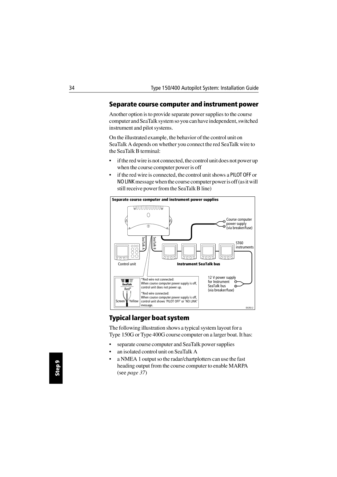
Separate course computer and instrument power
Typical larger boat system
Typical larger boat system
Connecting Nmea equipment
Course computer Nmea inputs/outputs
Course computer Nmea 1 and 2 inputs
Nmea 0183 received Information extracted
Connecting several items of Nmea equipment
Control unit Nmea inputs
SeaTalk/NMEA interface
Typical Nmea connections
Option 1 without SeaTalk/NMEA interface
GyroPlus yaw sensor
Connecting optional components
External alarm
Handheld remotes
Off switch
Connecting spool valves
Other manufacturers’ drive units
Setting-up the autopilot
Course computer connections
Regular checks
Maintenance
Fault-finding
Servicing
EMC, servicing and safety guidelines
Product support
Specifications
Course computer specifications
Control unit
Course computer specifications contd
Control unit functionality
Course computer Type 150G/400G Type 150/400 Type 100/300
Glossary
Term Meaning
VHF
Index
EMC
Type 150/400 Autopilot System Installation Guide
Index
Type 150/400 Autopilot System Installation Guide
Aft
Rudder position sensor template
Page
Limited Warranty Certificate
Warranty Limitations
Factory Service Centers
United States of America UK, Europe, Middle East, Far East

![]() SeaTalk bus
SeaTalk bus ![]() (via breaker/fuse)
(via breaker/fuse)