1.3 SPECIFICATIONS
Appendix 1 : Design Specification Model RAY210
General : FCC Part 80, ITU Radio Regulations Appendix 18. DOC CAT V
1.3.1 Electrical Specifications; |
|
Transmitter |
|
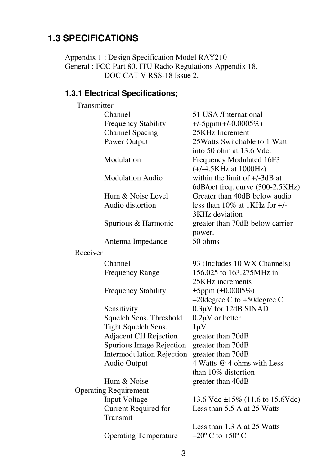
Channel | 51 USA /International |
Frequency Stability | |
Channel Spacing | 25KHz Increment |
Power Output | 25Watts Switchable to 1 Watt |
| into 50 ohm at 13.6 Vdc. |
Modulation | Frequency Modulated 16F3 |
| |
Modulation Audio | within the limit of |
| 6dB/oct freq. curve |
Hum & Noise Level | Greater than 40dB below audio |
Audio distortion | less than 10% at 1KHz for +/- |
| 3KHz deviation |
Spurious & Harmonic | greater than 70dB below carrier |
| power. |
Antenna Impedance | 50 ohms |
Receiver |
|
Channel | 93 (Includes 10 WX Channels) |
Frequency Range | 156.025 to 163.275MHz in |
| 25KHz increments |
Frequency Stability | ±5ppm (±0.0005%) |
| |
Sensitivity | 0.3µV for 12dB SINAD |
Squelch Sens. Threshold | 0.2µV or better |
Tight Squelch Sens. | 1µV |
Adjacent CH Rejection | greater than 70dB |
Spurious Image Rejection | greater than 70dB |
Intermodulation Rejection | greater than 70dB |
Audio Output | 4 Watts @ 4 ohms with Less |
| than 10% distortion |
Hum & Noise | greater than 40dB |
Operating Requirement |
|
Input Voltage | 13.6 Vdc ±15% (11.6 to 15.6Vdc) |
Current Required for | Less than 5.5 A at 25 Watts |
Transmit |
|
| Less than 1.3 A at 25 Watts |
Operating Temperature | |
3 |
|
