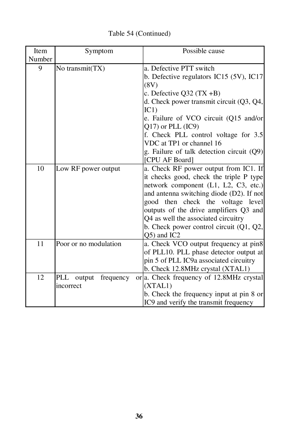
Table 54 (Continued)
Item | Symptom |
| Possible cause |
Number |
|
|
|
9 | No transmit(TX) |
| a. Defective PTT switch |
|
|
| b. Defective regulators IC15 (5V), IC17 |
|
|
| (8V) |
|
|
| c. Defective Q32 (TX +B) |
|
|
| d. Check power transmit circuit (Q3, Q4, |
|
|
| IC1) |
|
|
| e. Failure of VCO circuit (Q15 and/or |
|
|
| Q17) or PLL (IC9) |
|
|
| f. Check PLL control voltage for 3.5 |
|
|
| VDC at TP1 or channel 16 |
|
|
| g. Failure of talk detection circuit (Q9) |
|
|
| [CPU AF Board] |
10 | Low RF power output |
| a. Check RF power output from IC1. If |
|
|
| it checks good, check the triple P type |
|
|
| network component (L1, L2, C3, etc.) |
|
|
| and antenna switching diode (D2). If not |
|
|
| good then check the voltage level |
|
|
| outputs of the drive amplifiers Q3 and |
|
|
| Q4 as well the associated circuitry |
|
|
| b. Check power control circuit (Q1, Q2, |
|
|
| Q5) and IC2 |
11 | Poor or no modulation |
| a. Check VCO output frequency at pin8 |
|
|
| of PLL10. PLL phase detector output at |
|
|
| pin 5 of PLL IC9a associated circuitry |
|
|
| b. Check 12.8MHz crystal (XTAL1) |
12 | PLL output frequency | or | a. Check frequency of 12.8MHz crystal |
| incorrect |
| (XTAL1) |
|
|
| b. Check the frequency input at pin 8 or |
|
|
| IC9 and verify the transmit frequency |
36