Table
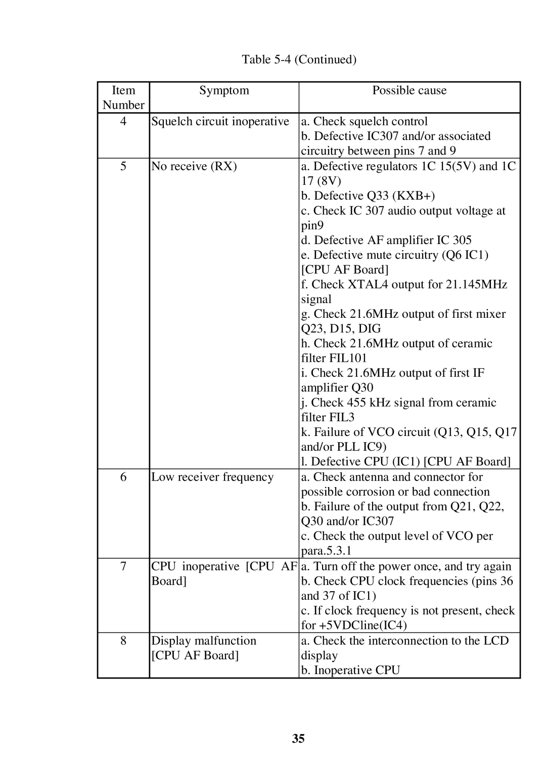
Item | Symptom | Possible cause |
Number |
|
|
4 | Squelch circuit inoperative | a. Check squelch control |
|
| b. Defective IC307 and/or associated |
|
| circuitry between pins 7 and 9 |
5 | No receive (RX) | a. Defective regulators 1C 15(5V) and 1C |
|
| 17 (8V) |
|
| b. Defective Q33 (KXB+) |
|
| c. Check IC 307 audio output voltage at |
|
| pin9 |
|
| d. Defective AF amplifier IC 305 |
|
| e. Defective mute circuitry (Q6 IC1) |
|
| [CPU AF Board] |
|
| f. Check XTAL4 output for 21.145MHz |
|
| signal |
|
| g. Check 21.6MHz output of first mixer |
|
| Q23, D15, DIG |
|
| h. Check 21.6MHz output of ceramic |
|
| filter FIL101 |
|
| i. Check 21.6MHz output of first IF |
|
| amplifier Q30 |
|
| j. Check 455 kHz signal from ceramic |
|
| filter FIL3 |
|
| k. Failure of VCO circuit (Q13, Q15, Q17 |
|
| and/or PLL IC9) |
|
| l. Defective CPU (IC1) [CPU AF Board] |
6 | Low receiver frequency | a. Check antenna and connector for |
|
| possible corrosion or bad connection |
|
| b. Failure of the output from Q21, Q22, |
|
| Q30 and/or IC307 |
|
| c. Check the output level of VCO per |
|
| para.5.3.1 |
7 | CPU inoperative [CPU AF | a. Turn off the power once, and try again |
| Board] | b. Check CPU clock frequencies (pins 36 |
|
| and 37 of IC1) |
|
| c. If clock frequency is not present, check |
|
| for +5VDCline(IC4) |
8 | Display malfunction | a. Check the interconnection to the LCD |
| [CPU AF Board] | display |
|
| b. Inoperative CPU |
35