5.3.7Weather Alert Frequency Adjustment (RECEIVER)
1)Connect an RF signal generator to the antenna connector. Set the RF signal generator as follows:
Frequency: 162.550MHz with no modulation
Output level: 60dB µ
2)Select the weather channel WX1.
3)Connect a frequency counter to TP1 on the RF Board and adjust RV6 to obtain 1050kHz
5.4TROUBLE SHOOTING GUIDE
Table
5.4.1 Master Reset
The first step in attempting to clear a problem associated with the general operation of this radio is to perform a MASTER RESET. This can be done by pressing the [FUNC] and [16] keys simultaneously, and while holding, turning the power on. This should be performed anytime a component or PCB within the radio is replaced. This function will clear the RAY210 memory and will return it to its factory settings.
It should be noted that
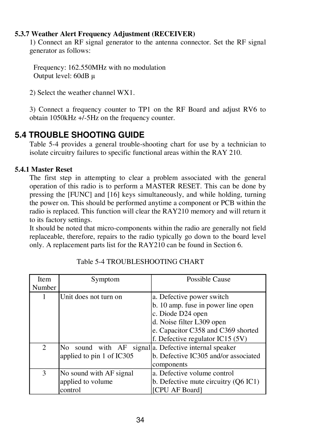
Table
Item | Symptom | Possible Cause |
Number |
|
|
1 | Unit does not turn on | a. Defective power switch |
|
| b. 10 amp. fuse in power line open |
|
| c. Diode D24 open |
|
| d. Noise filter L309 open |
|
| e. Capacitor C358 and C369 shorted |
|
| f. Defective regulator IC15 (5V) |
2 | No sound with AF signal | a. Defective internal speaker |
| applied to pin 1 of IC305 | b. Defective IC305 and/or associated |
|
| components |
3 | No sound with AF signal | a. Defective volume control |
| applied to volume | b. Defective mute circuitry (Q6 IC1) |
| control | [CPU AF Board] |
34