5.3.3Frequency Adjustment (TRANSMITTER)
1)Connect the coupler output to a frequency counter, set the radio on CH16 (156.800MHz), key to transmit, and read the indication on the frequency counter.
2)Adjust trimmer capacitor CV1 on the RF module for the desired frequency (156.800MHz) ±200Hz on the frequency counter.
5.3.4Modulation Adjustment (TRANSMITTER)
1)Connect the coupler output to an FM linear detector.
Connect an audio oscillator to the microphone connector and key to transmit.
2)Set the audio oscillator output to
3)Set the audio oscillator output to
5.3.5Power Output Adjustment
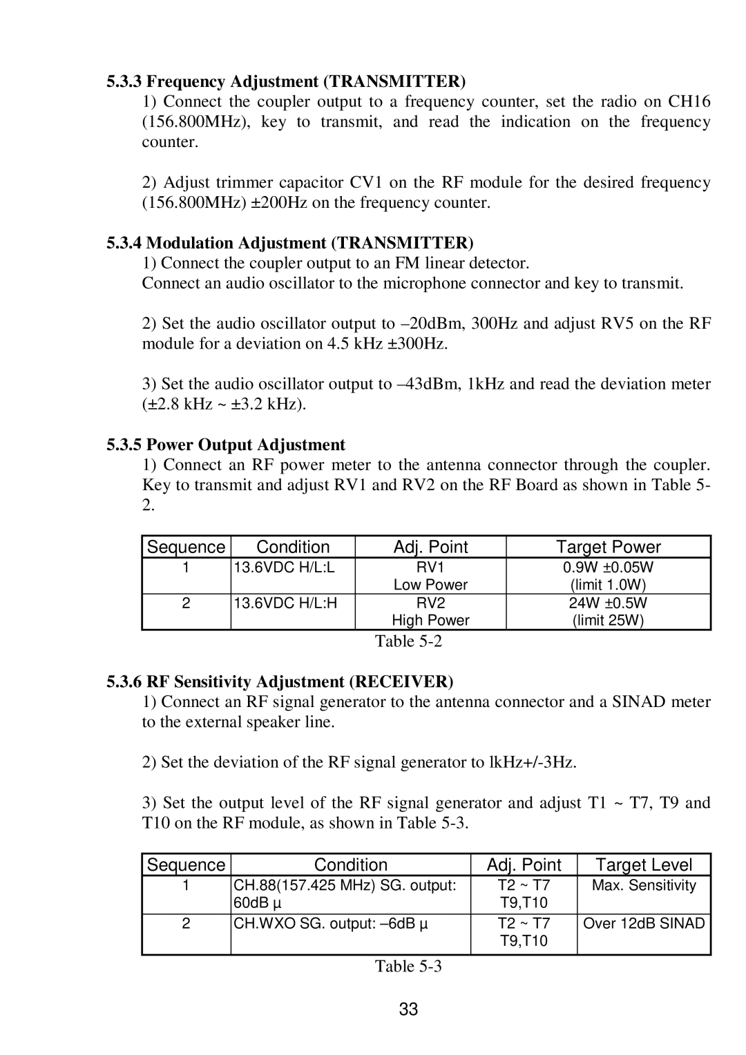
1)Connect an RF power meter to the antenna connector through the coupler. Key to transmit and adjust RV1 and RV2 on the RF Board as shown in Table 5- 2.
Sequence | Condition | Adj. Point | Target Power |
1 | 13.6VDC H/L:L | RV1 | 0.9W ±0.05W |
|
| Low Power | (limit 1.0W) |
2 | 13.6VDC H/L:H | RV2 | 24W ±0.5W |
|
| High Power | (limit 25W) |
Table
5.3.6RF Sensitivity Adjustment (RECEIVER)
1)Connect an RF signal generator to the antenna connector and a SINAD meter to the external speaker line.
2)Set the deviation of the RF signal generator to
3)Set the output level of the RF signal generator and adjust T1 ~ T7, T9 and T10 on the RF module, as shown in Table
Sequence | Condition | Adj. Point | Target Level |
1 | CH.88(157.425 MHz) SG. output: | T2 ~ T7 | Max. Sensitivity |
| 60dB µ | T9,T10 |
|
2 | CH.WXO SG. output: | T2 ~ T7 | Over 12dB SINAD |
|
| T9,T10 |
|
|
|
|
|
Table
33