SLAVE
Sw #3 - Master/SlaveOff - Designates the
On - Designates the unit as a slave (used for ganged
DHW
Sw #4 - Outdoor ResetOff - Minimum allowable Set Point of 105°F reduces potential of condensensing the boiler. On - Set Point can be reduced to 40°F for special applications (e.g. water source heat pumps, etc.)
Sw #5 - 8 - Reserved | Reserved for future use. |
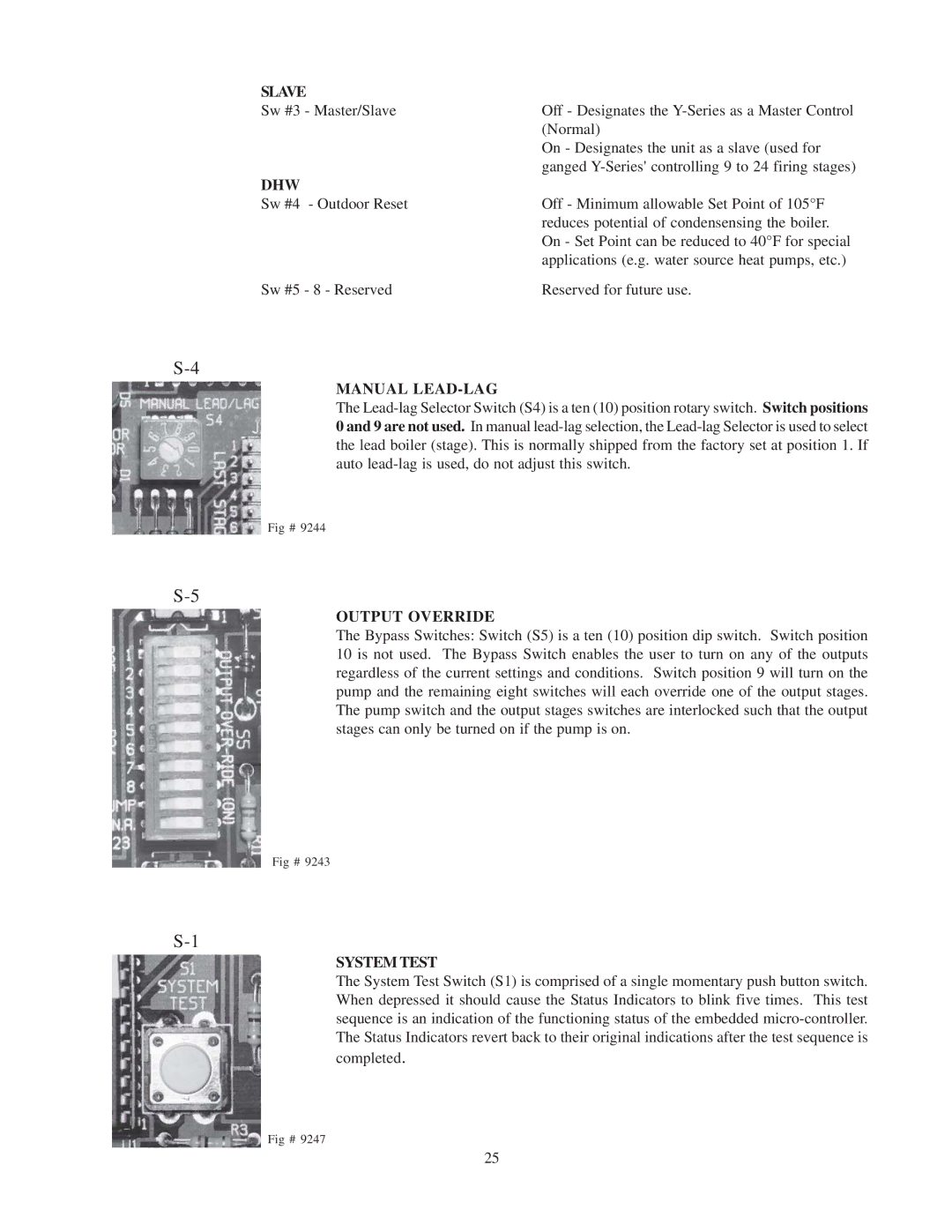
MANUAL LEAD-LAG
The
Fig # 9244
OUTPUT OVERRIDE
The Bypass Switches: Switch (S5) is a ten (10) position dip switch. Switch position 10 is not used. The Bypass Switch enables the user to turn on any of the outputs regardless of the current settings and conditions. Switch position 9 will turn on the pump and the remaining eight switches will each override one of the output stages. The pump switch and the output stages switches are interlocked such that the output stages can only be turned on if the pump is on.
Fig # 9243
SYSTEM TEST
The System Test Switch (S1) is comprised of a single momentary push button switch. When depressed it should cause the Status Indicators to blink five times. This test sequence is an indication of the functioning status of the embedded
completed.
Fig # 9247
25