Chapter 1: Connections and Setup
Rear Panel - J32C750
USB IN ![]()
AV2 | L - AUDIO - R |
| VIDEO |
10
11
|
| COMPONENT IN |
|
|
|
|
| ||
AC IN | HDMI/DVI | RGB IN |
|
|
|
| AUDIO IN | ANTENNA/ | DIGITAL AUDIO |
| IN | (PC) | L | R |
| AV IN | (RGB/DVI) | CABLE IN | OUT(COAXIAL) SERVICE |
|
|
| AUDIO |
|
|
|
|
|
|
|
| Y | Pb | Pr | VIDEO | L | R |
|
|
|
|
| VIDEO |
|
| AUDIO |
|
|
|
1 | 2 | 3 | 4 | 5 | 6 | 7 | 8 | 9 |
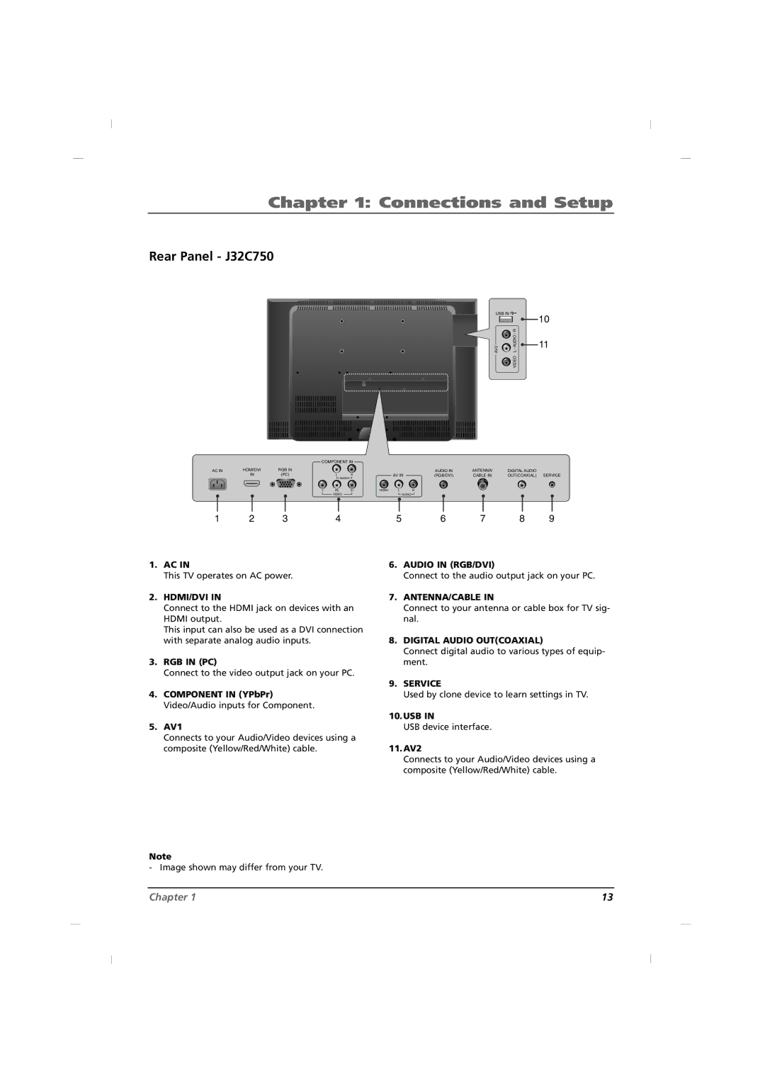
1.AC IN
This TV operates on AC power.
2.HDMI/DVI IN
Connect to the HDMI jack on devices with an HDMI output.
This input can also be used as a DVI connection with separate analog audio inputs.
3.RGB IN (PC)
Connect to the video output jack on your PC.
4.COMPONENT IN (YPbPr) Video/Audio inputs for Component.
5.AV1
Connects to your Audio/Video devices using a composite (Yellow/Red/White) cable.
6.AUDIO IN (RGB/DVI)
Connect to the audio output jack on your PC.
7.ANTENNA/CABLE IN
Connect to your antenna or cable box for TV sig- nal.
8.DIGITAL AUDIO OUT(COAXIAL)
Connect digital audio to various types of equip- ment.
9.SERVICE
Used by clone device to learn settings in TV.
10.USB IN
USB device interface.
11.AV2
Connects to your Audio/Video devices using a composite (Yellow/Red/White) cable.
Note
- Image shown may differ from your TV.
Chapter 1 | 13 |