Chapter 1: Connections and Setup
HDSTB Connection
-This TV can receive Digital
However, if you do receive Digital signals from a digital
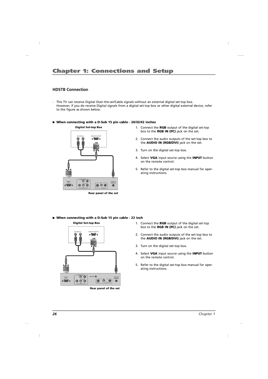
AWhen connecting with a D-Sub 15 pin cable - 26/32/42 inches
Digital
(R) AUDIO (L) |
1.Connect the RGB output of the digital
2.Connect the audio outputs of the
3. Turn on the digital
4. Select VGA input source using the INPUT button on the remote control.
5. Refer to the digital
COMPONENT IN |
|
|
| ||
RGB IN |
|
|
|
| AUDIO IN |
(PC) | L | R |
| AV1 | (RGB/DVI) |
| AUDIO |
|
|
|
|
Y | Pb | Pr | VIDEO | L | R |
| VIDEO |
|
|
| AUDIO |
Rear panel of the set
AWhen connecting with a D-Sub 15 pin cable - 22 inch
Digital
(R) AUDIO (L) |
1.Connect the RGB output of the digital
2.Connect the audio outputs of the
3. Turn on the digital
4. Select VGA input source using the INPUT button on the remote control.
5. Refer to the digital
COMPONENT IN |
|
|
| ||
RGB IN |
|
| SERVICE |
| AUDIO IN |
|
|
|
| ||
(PC) | L | R |
| AV1 | (RGB/DVI) |
| AUDIO |
|
|
| |
Y | Pb | Pr | VIDEO | L AUDIO R |
|
| VIDEO |
|
|
|
|
Rear panel of the set
26 | Chapter 1 |