INSTALLATION
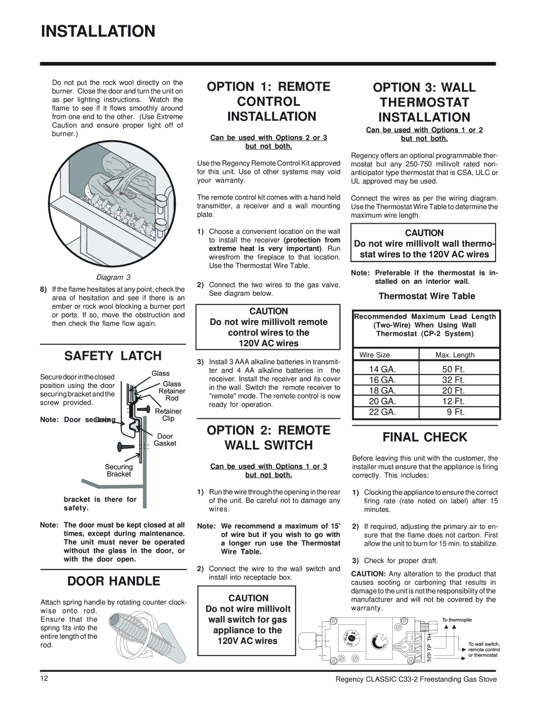
Do not put the rock wool directly on the burner. Close the door and turn the unit on as per lighting instructions. Watch the flame to see if it flows smoothly around from one end to the other. (Use Extreme Caution and ensure proper light off of burner.)
Diagram 3
8)If the flame hesitates at any point, check the area of hesitation and see if there is an ember or rock wool blocking a burner port or ports. If so, move the obstruction and then check the flame flow again.
SAFETY LATCH
Secure door in the closed position using the door securing bracket and the screw provided.
Note: Door securing
bracket is there for safety.
Note: The door must be kept closed at all times, except during maintenance. The unit must never be operated without the glass in the door, or with the door open.
DOOR HANDLE
Attach spring handle by rotating counter clock- wise onto rod.
Ensure that the spring fits into the entire length of the
rod.
OPTION 1: REMOTE
CONTROL
INSTALLATION
Can be used with Options 2 or 3
but not both.
Use the Regency Remote Control Kit approved for this unit. Use of other systems may void your warranty.
The remote control kit comes with a hand held transmitter, a receiver and a wall mounting plate.
1)Choose a convenient location on the wall to install the receiver (protection from extreme heat is very important). Run wiresfrom the fireplace to that location. Use the Thermostat Wire Table.
2)Connect the two wires to the gas valve. See diagram below.
CAUTION
Do not wire millivolt remote
control wires to the
120V AC wires
3)Install 3 AAA alkaline batteries in transmit- ter and 4 AA alkaline batteries in the receiver. Install the receiver and its cover in the wall. Switch the remote receiver to "remote" mode. The remote control is now ready for operation.
OPTION 2: REMOTE
WALL SWITCH
Can be used with Options 1 or 3
but not both.
1)Run the wire through the opening in the rear of the unit. Be careful not to damage any wires.
Note: We recommend a maximum of 15' of wire but if you wish to go with a longer run use the Thermostat Wire Table.
2)Connect the wire to the wall switch and install into receptacle box.
CAUTION
Do not wire millivolt wall switch for gas appliance to the 120V AC wires
OPTION 3: WALL
THERMOSTAT
INSTALLATION
Can be used with Options 1 or 2
but not both.
Regency offers an optional programmable ther- mostat but any
Connect the wires as per the wiring diagram. Use the Thermostat Wire Table to determine the maximum wire length.
CAUTION
Do not wire millivolt wall thermo- stat wires to the 120V AC wires
Note: Preferable if the thermostat is in- stalled on an interior wall.
Thermostat Wire Table
Recommended Maximum Lead Length
Thermostat
Wire Size | Max. Length | |
14 GA. | 50 Ft. | |
16 GA. | 32 Ft. | |
18 GA. | 20 Ft. | |
20 GA. | 12 Ft. | |
22 GA. | 9 Ft. | |
|
|
|
|
|
|
FINAL CHECK
Before leaving this unit with the customer, the installer must ensure that the appliance is firing correctly. This includes:
1)Clocking the appliance to ensure the correct firing rate (rate noted on label) after 15 minutes.
2)If required, adjusting the primary air to en- sure that the flame does not carbon. First allow the unit to burn for 15 min. to stabilize.
3)Check for proper draft.
CAUTION: Any alteration to the product that causes sooting or carboning that results in damage to the unit is not the responsibility of the manufacturer and will not be covered by the warranty.
12 | Regency CLASSIC |