INSTALLATION
Wiring
11)Remove the dummy plug from the right side of the bottom shield or pedestal and install the supplied fan switch.
12)Attach hot wire from power cord to the thermodisc.
13)Slide the thermodisc under the bracket.
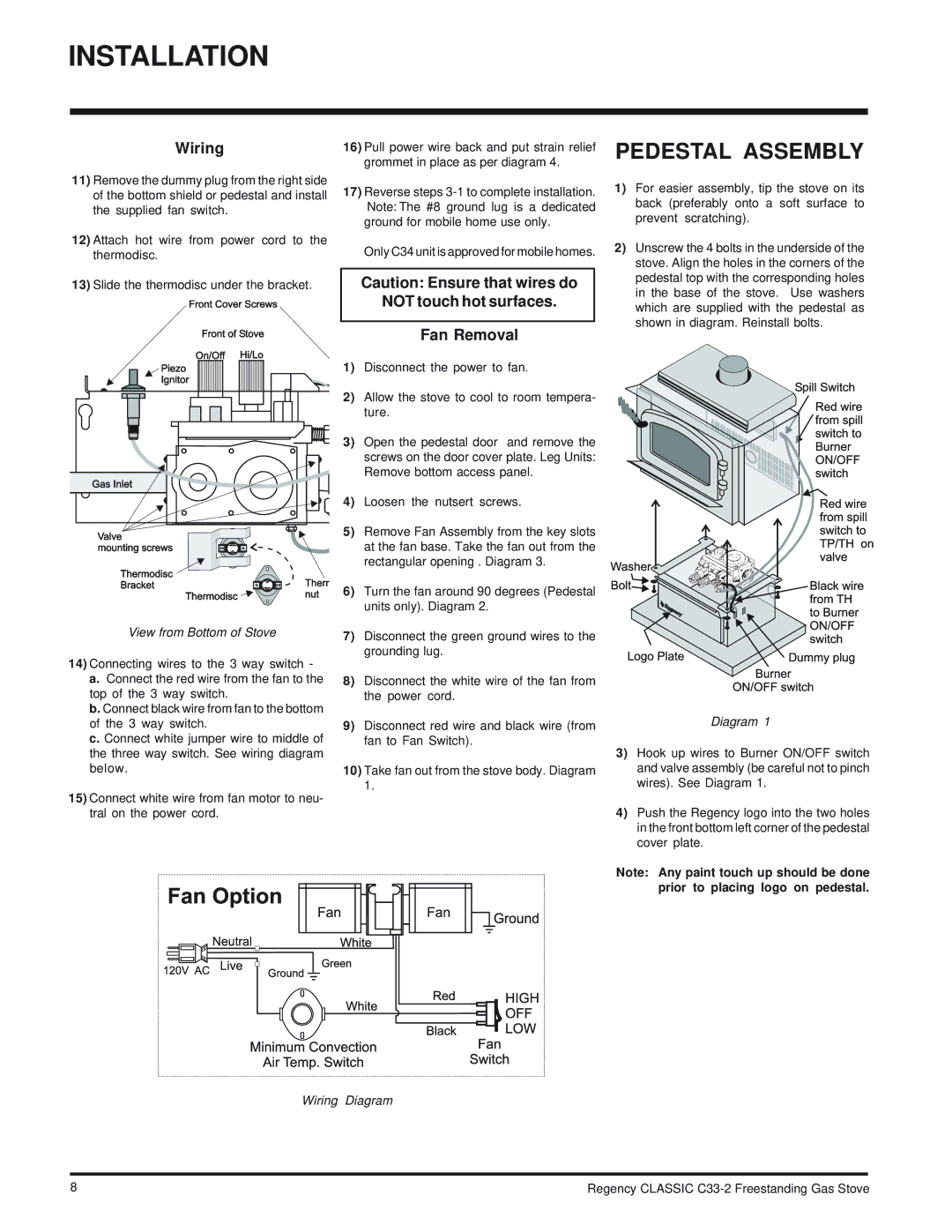
View from Bottom of Stove
14)Connecting wires to the 3 way switch -
a.Connect the red wire from the fan to the top of the 3 way switch.
b.Connect black wire from fan to the bottom of the 3 way switch.
c.Connect white jumper wire to middle of the three way switch. See wiring diagram below.
15)Connect white wire from fan motor to neu- tral on the power cord.
16)Pull power wire back and put strain relief grommet in place as per diagram 4.
17)Reverse steps
Only C34 unit is approved for mobile homes.
Caution: Ensure that wires do
NOT touch hot surfaces.
Fan Removal
1)Disconnect the power to fan.
2)Allow the stove to cool to room tempera- ture.
3)Open the pedestal door and remove the screws on the door cover plate. Leg Units: Remove bottom access panel.
4)Loosen the nutsert screws.
5)Remove Fan Assembly from the key slots at the fan base. Take the fan out from the rectangular opening . Diagram 3.
6)Turn the fan around 90 degrees (Pedestal units only). Diagram 2.
7)Disconnect the green ground wires to the grounding lug.
8)Disconnect the white wire of the fan from the power cord.
9)Disconnect red wire and black wire (from fan to Fan Switch).
10)Take fan out from the stove body. Diagram 1.
PEDESTAL ASSEMBLY
1)For easier assembly, tip the stove on its back (preferably onto a soft surface to prevent scratching).
2)Unscrew the 4 bolts in the underside of the stove. Align the holes in the corners of the pedestal top with the corresponding holes in the base of the stove. Use washers which are supplied with the pedestal as shown in diagram. Reinstall bolts.
Diagram 1
3)Hook up wires to Burner ON/OFF switch and valve assembly (be careful not to pinch wires). See Diagram 1.
4)Push the Regency logo into the two holes in the front bottom left corner of the pedestal cover plate.
Note: Any paint touch up should be done prior to placing logo on pedestal.
Wiring Diagram
8 | Regency CLASSIC |