INSTALLATION

NOTE: For Snorkel terminations in ABOVE grade installations, follow national or local code requirements.

Below Grade Snorkel Installation

If the Snorkel Termination must be installed below grade, i.e. basement application, proper drainage must be provided to pre- vent water from entering the Snorkel Ter- mination. Refer to Dura-Vent Installation instructions for details.. Do not attempt to enclose the Snorkel within the wall, or any other type of enclosure.

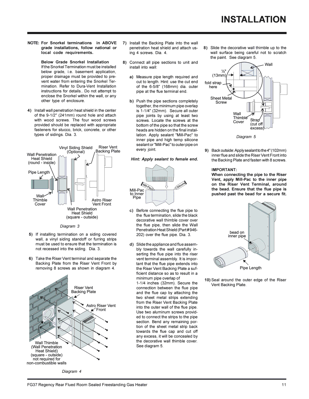
4)Install wall penetration heat shield in the center of the 9-1/2" (241mm) round hole and attach with wood screws. The four wood screws provided should be replaced with appropriate fasteners for stucco, brick, concrete, or other types of sidings. Dia. 3.

Diagram 3

5)If installing termination on a siding covered wall, a vinyl siding standoff or furring strips must be used to ensure that the termination is not recessed into the siding. Dia. 3.

6)Take the Riser Vent terminal and separate the Backing Plate from the Riser Vent Front by removing 8 screws as shown in diagram 4.

Diagram 4

7)Install the Backing Plate into the wall penetration heat shield and attach us- ing 4 screws. Dia. 4.

8)Connect all pipe sections to unit and install into wall:

a)Measure pipe length required and cut to length. Hint: use the cut end of the 6-5/8" (168mm) dia. outer pipe at the flue terminal end.

b)Push the pipe sections completely together, the minimum pipe overlap is 1-1/4" (32mm). Secure all outer pipe joints by using at least two screws. Locate the screws at the bottom of the pipe so that the screw heads are hidden on the final instal- lation. Apply sealant "Mill-Pac" to inner pipe and high temp silicone sealant or "Mill-Pac" to outer pipe on every joint.

Hint: Apply sealant to female end.

c)Before connecting the flue pipe to the flue termination, slide the black decorative wall thimble cover over the flue pipe, then slide the Wall Penetration Heat Shield (Part # 946- 202) over the flue pipe. Dia. 3.

d)Slide the appliance and flue assem- bly towards the wall carefully in- serting the flue pipe into the riser vent terminal assembly. It is impor- tant that the flue pipe extends into the Riser Vent Backing Plate a suf- ficient distance so as to result in a minimum pipe overlap of

1-1/4 inches (32mm). Secure the connection between the flue pipe and the flue cap by attaching the two sheet metal strips extending from the Riser Vent Backing Plate into the outer wall of the flue pipe. Use two aluminum screws provid- ed to connect the strips to the pipe section. Bend any remaining por- tion of the sheet metal strip back towards the flue cap and cut off any excess, it will be concealed by the decorative wall thimble cover. See diagram 5.

8)Slide the decorative wall thimble up to the wall surface being careful not to scratch the paint. See diagram 5.

Diagram 5

9)Backoutside:Applysealanttothe4"(102mm) inner flue and slide the Riser Vent Front into the Backing Plate and fasten with 8 screws.

IMPORTANT:

When connecting the pipe to the Riser Vent, apply Mill-Pac to the inner pipe on the Riser Vent Terminal, around the bead. Ensure that the flue pipe is pushed past the bead for a secure fit.

10)Seal around the outer edge of the Riser Vent Backing Plate.

FG37 Regency Rear Flued Room Sealed Freestanding Gas Heater

11

Page 11
Image 11
Regency FG37-NG, FG37-LPG installation manual Below Grade Snorkel Installation, Hint Apply sealant to female end

FG37-NG, FG37-LPG specifications

The Regency FG37-LPG and FG37-NG are premium gas fireplaces that blend elegance with cutting-edge technology, making them ideal for modern homes. Designed by Regency, a leader in the fireplace industry, these models offer both aesthetic appeal and highly efficient heating capabilities.

The FG37-LPG is powered by liquid propane, while the FG37-NG utilizes natural gas, providing versatile options to meet different customer needs. Both models feature a sleek, contemporary design that complements various interior styles, making them a focal point in any living space. The large viewing area allows for an expansive display of flames, contributing to a warm, inviting atmosphere.

One of the standout features of the Regency FG37 series is its advanced heating technology. The fireplaces employ a high-efficiency burner system that maximizes heat output while minimizing gas consumption. This efficiency not only leads to lower energy bills but also reduces environmental impact, aligning with sustainability goals.

Additionally, the Regency FG37 models feature advanced flame control technology. Users can easily adjust the flame intensity, allowing for a custom heating experience that suits personal preferences and room sizes. This versatility makes them suitable for a variety of applications, from cozy family rooms to expansive open-concept spaces.

For added convenience, the fireplaces are equipped with a modern electronic ignition system, ensuring reliable and hassle-free startup. Customers appreciate the included remote control, which provides effortless operation from the comfort of their seats. As an optional upgrade, the Regency Smart Home Control system allows for integration with smart home devices, enabling users to manage their fireplace from their smartphones or tablets.

Safety is paramount in the design of the FG37-LPG and FG37-NG. Both models come with a built-in safety shutoff valve, ensuring that the gas supply is automatically cut off in the event of an emergency. The units also feature a glass door that remains cool to the touch, providing peace of mind for households with pets and children.

Overall, the Regency FG37-LPG and FG37-NG epitomize the perfect merger of style, efficiency, and safety. With their striking design, advanced technologies, and user-friendly features, these gas fireplaces are an excellent choice for anyone seeking to enhance their home with the luxury and warmth of a modern fireplace.